Catheter

A probe and tube technology, applied in the field of probes, can solve problems such as increasing obstacles, and achieve the effect of increasing the number

Active Publication Date: 2015-04-22
JAPAN LIFELINE CO LTD
View PDF4 Cites 0 Cited by
  • Summary
  • Abstract
  • Description
  • Claims
  • Application Information

AI Technical Summary

Problems solved by technology

However, in the above-mentioned conventional probes, the plate spring inserted into the tube becomes an obstacle when increasing the number of lead wires to be inserted.

Method used


Image

  • Catheter
  • Catheter
  • Catheter

Examples


Embodiment approach 1

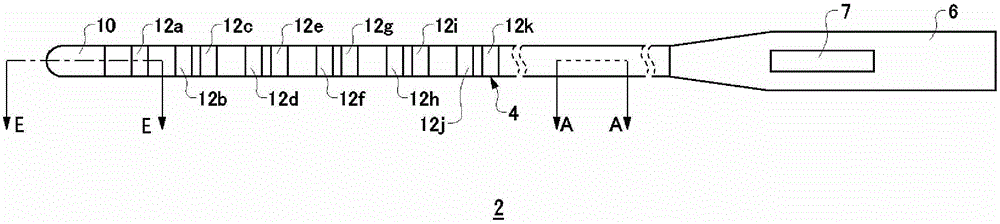
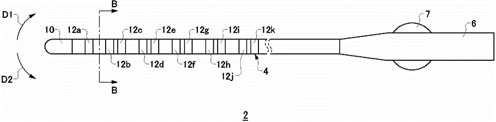
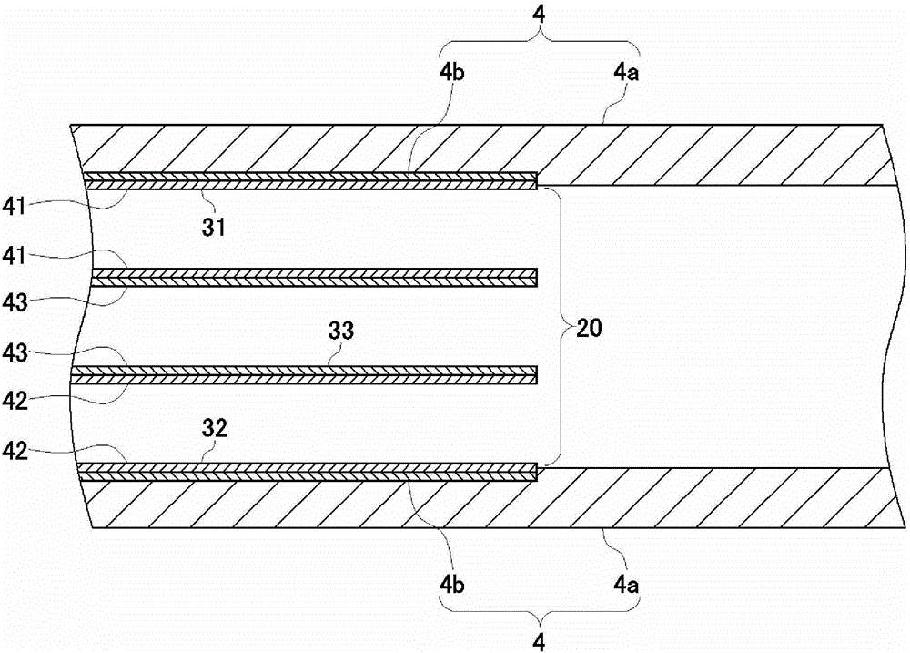
[0023] The probe according to Embodiment 1 is an electrode-type probe capable of end deflection operation, and can be used for diagnosis or treatment of cardiac arrhythmia, for example. figure 1 is a schematic side view of the probe according to Embodiment 1, figure 2 It is a schematic plan view of the probe according to Embodiment 1. image 3 yes figure 1 A brief sectional view on line A-A of . Among them, in image 3 The illustration of the operation wires 50a and 50b is omitted in .

[0024] Such as figure 1 and figure 2 As shown, the probe 2 according to Embodiment 1 includes a tubular member 4, a handle 6, a terminal chip electrode 10, and a plurality of ring-shaped electrodes 12a to 12k (hereinafter, the ring-shaped electrodes 12a to 12k are collectively referred to as "rings" as appropriate. shape electrode 12").

[0025] The probe 2 has a terminal sheet electrode 10 and a ring electrode 12 at the distal end of the tubular member 4 . For example, the terminal ...


PUM


Abstract

Disclosed is a catheter provided with: a tube member (4); a pair of bar springs (22a and 22b) provided inside the tube member (4) along the central axis (X1) thereof, one of said bar springs being offset from the central axis (X1) and the other being offset from the central axis (X1) in the opposite direction; control-wire insertion passages (31 and 32) provided inside the tube member (4) along the central axis (X1) thereof, located respectively on one side (H1) and the other side (H2) of a virtual plane (H) that passes through the central axes (X2 and X3) of the two bar springs (22a and 22b); and control wires (50a and 50b) slidably inserted into the control-wire insertion passages (31 and 32), one end of each control wire being connected near the distal end of the tube member (4).

Description

technical field [0001] The present invention relates to probes. More specifically, the present invention relates to a probe capable of easily changing the direction near the distal end inserted into a body cavity by manipulating an operating portion disposed outside the body on the proximal end side. Background technique [0002] In a probe such as an electrode-type probe inserted into the heart through a blood vessel, the probe inserted into the body is deflected by operating the operation part mounted on the proximal end (base end or hand side) of the probe disposed outside the body. The orientation of the distal end (tip) of the needle. As a mechanism for deflecting the distal end of the probe, for example, Patent Document 1 discloses a structure including a leaf spring and a pair of operation wires arranged on both sides of the leaf spring, and by pulling the operation Use the wire to deflect the distal end in both directions. In the case of deflecting the distal end ...

Claims


Application Information

Patent Timeline
Patent Type & Authority Patents(China)
IPC IPC(8): A61M25/00
CPCA61B18/1492A61M25/0147A61M25/0144A61M25/0136A61B5/6869A61B5/6852A61M2025/004A61M2025/0036A61B5/042A61B5/283A61M25/01A61M25/09
Inventor 森谦二
Owner JAPAN LIFELINE CO LTD
Why Eureka
Try Eureka