
Screen and screen unit

A technology for screens and substrates, used in projection devices, optics, instruments, etc., can solve the problems of display defects, easy static electricity on the screen, and reduced reflectivity of reflective films.

Active Publication Date: 2013-01-30
SEIKO EPSON CORP
View PDF5 Cites 0 Cited by
  • Summary
  • Abstract
  • Description
  • Claims
  • Application Information

AI Technical Summary

Problems solved by technology

In such a case, there is a problem that the reflective film is scratched in appearance, and as a result, the projected light from the projector cannot be reflected normally at the scratched part, resulting in a display defect.
However, the same problem arises because the front and back of the screen overlap each other at the portion where the winding step preventing member is not attached.
[0006] In addition, when the screen is rolled up so that the front surface and the back surface come into contact, the screen is easily charged with static electricity by repeatedly winding and unwinding (extracting) the screen and repeatedly contacting and separating the front surface and the back surface.
Therefore, there is a problem that dust in the use environment adheres to the front and back of the screen, reducing the reflectivity of the reflective film.

Method used


Image

  • Screen and screen unit
  • Screen and screen unit
  • Screen and screen unit

Examples


Embodiment approach

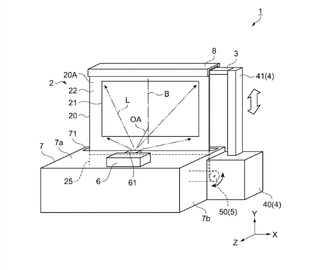
[0036] figure 1 It is a diagram schematically showing the screen device 1 according to the embodiment. Reference figure 1 The schematic structure of the screen device 1 of this embodiment will be briefly described.

[0037] The screen device 1 of this embodiment is a reflective screen device 1 and is a type of device that is installed on the ground or the like and used. In the screen device 1, a substantially rectangular screen is drawn upward (in a direction substantially perpendicular to the ground) from the inside of the box-shaped housing 7 formed in a rectangular parallelepiped shape by the operation of the retractable mechanism part 4 and the winding mechanism part 5 2. The screen 2 stands up with respect to the ground and becomes a usable state. Furthermore, the screen 2 reflects the projection light L emitted from the projector 6 provided in the housing 7 toward the viewer. In addition, the details of the screen device 1 will be described later.

[0038] In contain figu...


PUM


Abstract

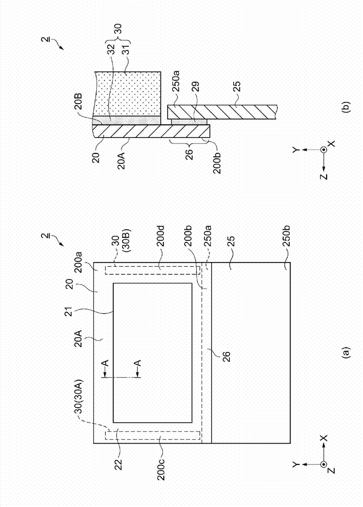
A screen reflects projection light for display. The screen has a screen base designed to be wound and including a first surface (front surface) and a second surface (rear surface) on the side opposite to the front surface. The front surface contains a display area that has a reflection film on which the projection light is reflected. The screen further has a flexible protection member which is disposed on the portion of the rear surface corresponding to the outside of the display area in the width direction of the display area, and extends through substantially the full length of the display area in the winding direction of the display area. The front surface is positioned outside when the screen base is wound.

Description

Technical field [0001] The invention relates to a screen and a screen device. Background technique [0002] Conventionally, there has been known a screen device that uses a screen to reflect projection light projected from a projection display device such as a projector to display an image. Patent Document 1 discloses the following: at both ends of the direction orthogonal to the direction in which the screen main body part and the non-screen main body part are joined and arranged on the back side of the screen, the first end and the second end are not connected to each other. Where the joined regions overlap, a first winding step prevention member and a second winding step prevention member are installed. Thereby, it is possible to provide a screen that can be wound and stored without the striped winding steps generated on the screen due to the step difference of the joint portion between the screen main body and the non-screen main body, and It has good flatness when used. [...

Claims


Application Information

Patent Timeline
Patent Type & Authority Applications(China)
IPC IPC(8): G03B21/58
CPCG03B21/58
Inventor 青木和雄
Owner SEIKO EPSON CORP
Learn More