Excitation control device, excitation control method, and synchronous rotating equipment using them
A technology of synchronous rotation and excitation control, which is applied in the model/simulation of control purposes, controlling generators and control systems through magnetic field changes, and can solve problems such as difficult to manufacture factories and implement load tests.
- Summary
- Abstract
- Description
- Claims
- Application Information
AI Technical Summary
Problems solved by technology
Method used
Image
Examples
Embodiment approach 1
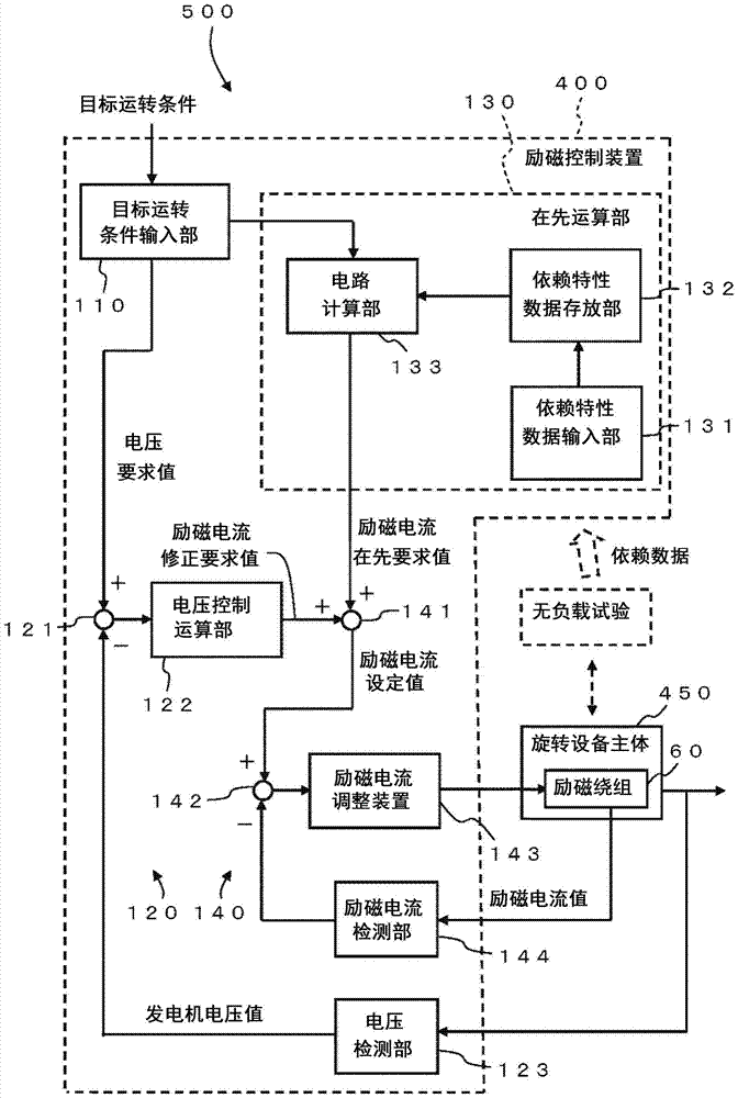
[0031] figure 1 It is a block diagram showing the structure of the synchronous rotating machine of Embodiment 1. The synchronous rotating machine 500 has a rotating machine main body 450 and an excitation control device 400 . The details of the structure of the synchronous rotating device 500 will be described later.
[0032] figure 2 It is a schematic quarter partial transverse cross-sectional view of the rotary device main body of the synchronous rotary device according to the first embodiment. image 3 It is a connection diagram of the field winding of the synchronous rotating machine of Embodiment 1. Figure 4 It is a wiring diagram of the armature winding of the synchronous rotating machine of Embodiment 1.
[0033] Such as figure 2 As shown, the reluctance type multi-phase synchronous rotating equipment (hereinafter simply referred to as "rotating equipment main body") 450 of this embodiment is, for example, a three-phase synchronous generator. The rotor 10 and t...
Embodiment approach 2
[0121] Figure 10 It is a block diagram showing the structure of the synchronous rotating machine of Embodiment 2.
[0122] This embodiment is a modification of the first embodiment. The main control variable in Embodiment 1 is generator voltage, but the main control variable in Embodiment 2 is power factor. Therefore, the excitation control device 400 of this embodiment includes the power factor detection unit 223 . In addition, the field control device 400 includes a power factor control computing unit 222 instead of the voltage control computing unit 122 .
[0123] The target operating condition input unit 110 outputs the required power factor value to the first subtraction unit 221 . The first subtraction unit 221 subtracts the generator power factor value fed back from the power factor detection unit 223 from the required power factor value from the target operating condition input unit 110 to output a power factor deviation.
[0124] The power factor control calculat...
Embodiment approach 3
[0130] Figure 11 It is a block diagram showing the structure of the synchronous rotating machine of Embodiment 3.
[0131] This embodiment is a modification of the first embodiment. The synchronous rotating machine 500 in this embodiment is a synchronous motor.
[0132] In the case of a synchronous motor, the target operating condition is, for example, torque. The main control quantity is also torque.
[0133] In this embodiment, the excitation control device 400 has an output detection unit 324 for detecting the output of the synchronous rotating machine 500, a rotation speed detection unit 325 for detecting the rotation speed, a torque calculation unit 323 for calculating torque from the output and the rotation speed, and a torque control calculation unit. 322.
[0134] In addition, since it is the synchronous rotating machine 500, the rotation speed basically corresponds to the rotation speed of the power supply frequency, and the rotation speed detection unit 325 does...
PUM
 Abstract
Description
Claims
Application Information
 - R&D
- Intellectual Property
- Life Sciences
- Materials
- Tech Scout
- Unparalleled Data Quality
- Higher Quality Content
- 60% Fewer Hallucinations
Browse by: Latest US Patents, China's latest patents, Technical Efficacy Thesaurus, Application Domain, Technology Topic, Popular Technical Reports.
© 2025 PatSnap. All rights reserved.Legal|Privacy policy|Modern Slavery Act Transparency Statement|Sitemap|About US| Contact US: help@patsnap.com


