Transmission method of uplink control information, user equipment and base station

A technology for controlling information and user equipment, applied in the field of communication, can solve problems such as resource waste and unfavorable system performance, and achieve the effect of reducing waste and optimizing decoding performance

Active Publication Date: 2019-01-01
FUJITSU LTD
View PDF4 Cites 0 Cited by
  • Summary
  • Abstract
  • Description
  • Claims
  • Application Information

AI Technical Summary

Problems solved by technology

However, in the existing system, the uplink reference signal still occupies two OFDM / SC-FDMA symbols in one subframe, which leads to waste of resources and is not conducive to further improving system performance

Method used


Image

  • Transmission method of uplink control information, user equipment and base station
  • Transmission method of uplink control information, user equipment and base station
  • Transmission method of uplink control information, user equipment and base station

Examples


Embodiment 1

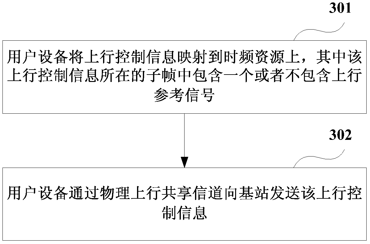
[0064] An embodiment of the present invention provides a method for transmitting uplink control information, which is described from a user equipment side. image 3 is a schematic flowchart of a method for transmitting uplink control information according to an embodiment of the present invention, as shown in image 3 As shown, the transfer method includes:

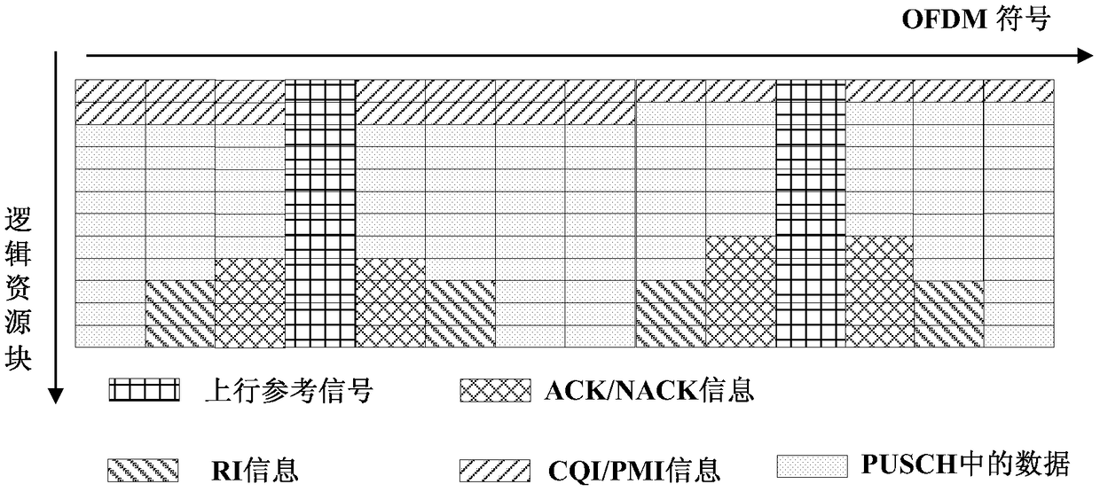
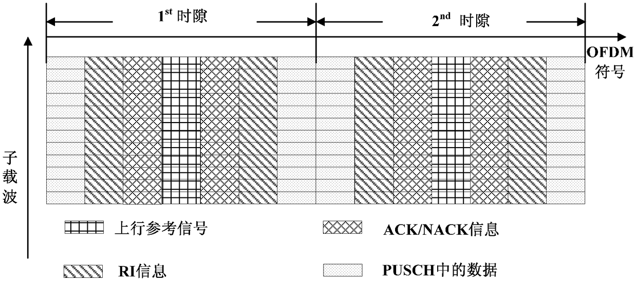
[0065] Step 301, the user equipment maps uplink control information to time-frequency resources, wherein the subframe where the uplink control information is located contains one or does not contain an uplink reference signal;

[0066] Step 302, the user equipment sends the uplink control information to the base station through the physical uplink shared channel.

[0067] In this embodiment, the uplink reference signal may be a demodulation reference signal (DMRS, Demodulation Reference Signal) and a sounding reference signal (SRS, Sounding Reference Signal), or other reference signals. The present invention is not limi...

Embodiment 2

[0160] The embodiment of the present invention provides a method for transmitting uplink control information, which is described from the side of the base station, and the same content as that of Embodiment 1 will not be repeated here.

[0161] Figure 24 is a schematic flowchart of a method for transmitting uplink control information according to an embodiment of the present invention, as shown in Figure 24 As shown, the transfer method includes:

[0162] Step 2401, the base station receives the uplink control information sent by the user equipment through the physical uplink shared channel, wherein the subframe where the uplink control information is located contains one or does not contain an uplink reference signal;

[0163] Step 2402, the base station demodulates the physical uplink shared channel to obtain uplink control information.

[0164] In this embodiment, the uplink control information may include first uplink control information, second uplink control informat...

Embodiment 3

[0169] An embodiment of the present invention provides a user equipment, which corresponds to the method for transmitting uplink control information described in Embodiment 1, and the same content as Embodiment 1 will not be described again.

[0170] Figure 25 is a schematic diagram of the structure of the user equipment according to the embodiment of the present invention, such as Figure 25 As shown, the user equipment 2500 includes: a mapping unit 2501 and a sending unit 2502 . For other components of the user equipment 2500, reference may be made to existing technologies.

[0171] Wherein, the mapping unit 2501 is used to map the uplink control information to time-frequency resources, wherein the subframe where the uplink control information is located contains one or no uplink reference signal; the sending unit 2502 sends the uplink control information to the base station through the physical uplink shared channel information.

[0172]In one embodiment, the mapping un...


PUM


Abstract

Embodiments of the present invention provide a method for transmitting uplink control information, user equipment, and a base station. The transmission method includes: the user equipment maps the uplink control information to time-frequency resources, wherein the subframe where the uplink control information is located contains one or no uplink reference signal (301); the user equipment sends a physical uplink shared channel to The base station sends the uplink control information (302). Through the embodiments of the present invention, the uplink reference signal occupies only one or no Orthogonal Frequency Division Multiplexing (OFDM) symbol in a subframe, which can reduce the waste of resources; and correspondingly change the resource mapping of the uplink control information, which can Get better decoding performance.

Description

technical field [0001] The present invention relates to a communication field, in particular to a method for transmitting uplink control information, user equipment and a base station. Background technique [0002] In the current E-UTRA (Evolved UMTS Terrestrial Radio Access) system, OFDM technology is used for downlink, and SC-OFDM technology is used for uplink. During uplink transmission, the user can send uplink control information (UCI, Uplink control information). The uplink control information may include ACK / NACK feedback information in the hybrid retransmission mechanism, Rank Indication (RI, Rank Indication) information related to the channel state, channel quality information (CQI, Channel quality information) and precoding matrix information (PMI, Precoding matrix information). [0003] The uplink control information can be sent periodically or aperiodically, for example, based on a trigger. The uplink control information may be sent through a physical uplink c...

Claims


Application Information

Patent Timeline
Patent Type & Authority Patents(China)
IPC IPC(8): H04L1/16H04J11/00
CPCH04L5/0048H04L1/1861H04L1/1671H04L5/0007H04L5/0055H04L5/0058
Inventor 王轶张磊
Owner FUJITSU LTD
Why Eureka
Try Eureka