Eureka AIR delivers breakthrough ideas for toughest innovation challenges, trusted by R&D personnel around the world.

Energy-saving back-filling mechanism

A technology for ejecting plates and runners, which is applied in the field of plastic molds, can solve the problems of high mold processing costs, complex mold structures, and low production efficiency, and achieve the goals of shortening the molding cycle, shortening the length of runners, and improving production efficiency. Effect

Active Publication Date: 2015-12-16
KUNSHAN XINTAILI PRECISION COMPONENTS CO LTD
View PDF3 Cites 0 Cited by
  • Summary
  • Abstract
  • Description
  • Claims
  • Application Information

AI Technical Summary

Problems solved by technology

The mold structure is more complex, the mold processing cost is higher; the runner is longer, the cooling cycle is longer during molding, and the production efficiency is low

Method used


Image

  • Energy-saving back-filling mechanism
  • Energy-saving back-filling mechanism
  • Energy-saving back-filling mechanism

Examples


Embodiment Construction

[0015] The preferred embodiments of the present invention will be described in detail below in conjunction with the accompanying drawings, so that the advantages and features of the present invention can be more easily understood by those skilled in the art, so as to define the protection scope of the present invention more clearly.

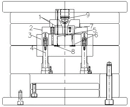
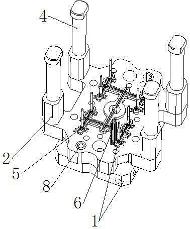
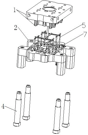
[0016] see Figure 1 to Figure 3 , the embodiment of the present invention includes:

[0017] An energy-saving reverse pouring mechanism, comprising: a runner plate 1, an ejector plate 2, a female mold core 3, a tension rod 4, a runner 5, a thimble 6, a thimble cover plate 7, a guide post guide sleeve 8 and a main filling nozzle 9.

[0018] The runner plate 1, the ejector plate 2, and the female die core 3 are connected sequentially from top to bottom. The upper end of the tension rod 4 passes through the female die core 3 and is connected to the ejector plate 2. In this embodiment, the upper end of the tension rod 4 is equipped with a shutter, ...


PUM


Abstract

The invention discloses an energy-saving back-filling mechanism. A runner system and an ejection system are designed in one assembly, wherein the runner system is designed in the ejection system; the runner system can be designed on the back of a die core; a runner plate penetrates through the ejection system and is in fit with the die core to form a runner, so that the length of the runner is reduced on the premise of no influence on the ejection mechanism; after the runner system and the ejection system are integrated to be a whole body, the advantages are characterized in that the length of the runner is reduced, the wastes are reduced, the forming period is shortened, the production cost is saved, the production efficiency is improved, and the purposes of saving energy and protecting environment are achieved.

Description

technical field [0001] The invention relates to the field of plastic molds, in particular to an energy-saving backfill mechanism. Background technique [0002] In order to improve the appearance of the product, customers are generally unwilling to design the glue inlet on the appearance of the product. For this kind of strict requirement, we will choose banana glue when designing the mould. But this glue mouth has a limitation, the position of the product side and the glue mouth cannot be too far, this limitation cannot meet the complex and changeable products. When the shape of the product is relatively large, use banana glue to arrange the outside of the product, and short shots will appear in the middle of the product. When a product is small and has sliders on all sides, the customer requires the appearance of the product without glue entry points. Neither of these two cases can be realized with banana glue ports. At this time, we will choose a reverse pouring three-p...

Claims


Application Information

Patent Timeline
Patent Type & Authority Applications(China)
IPC IPC(8): B29C45/27B29C45/33B29C45/40
CPCB29C45/0025B29C45/27B29C45/332B29C45/401
Inventor 张晓亮张雄杰
Owner KUNSHAN XINTAILI PRECISION COMPONENTS CO LTD
Why Eureka
Eureka Blog
Learn More