Material tray bottom lifting mechanism with detecting device

A detection device and material tray technology, applied in the direction of conveyor control devices, conveyor objects, transportation and packaging, etc., can solve problems such as safety, hidden dangers, inconvenient refueling, etc., and achieve good safety, high degree of automation, high efficiency effect

Inactive Publication Date: 2015-12-16
BOZHON PRECISION IND TECH CO LTD
View PDF6 Cites 2 Cited by
  • Summary
  • Abstract
  • Description
  • Claims
  • Application Information

AI Technical Summary

Problems solved by technology

[0002] On the assembly line, when the manipulator needs to replace the material, the material is in the work area of ​​the manipulator, which is inconvenient to change the material, affects the work of the manipulator, and has potential safety hazards; a device that can automatically feed and unload the material tray is required, and for material tray transportation During the process, the lifting mechanism is very important. This lifting mechanism must be able to receive and lift the material tray delivered by the conveying device to the working area of ​​the manipulator. After the manipulator completes the grabbing, it can descend to the bottom of the conveying device to pick up and unload the material, thus Realize uninterrupted conveying of loading and unloading, but there is no such lifting mechanism at present

Method used


Image

  • Material tray bottom lifting mechanism with detecting device
  • Material tray bottom lifting mechanism with detecting device

Examples


Embodiment Construction

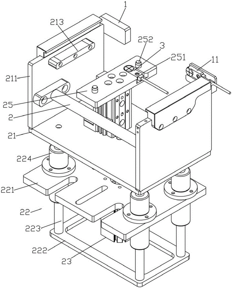
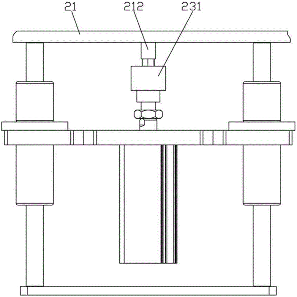
[0016] Examples, see e.g. Figures 1 to 2 As shown, a lifting mechanism at the bottom of a material tray with a detection device includes a base 22, a lifting cylinder 23 is fixed in the base 22, and the push rod of the lifting cylinder 23 passes through the base top plate 221 of the base 22 vertically upwards and is fixed on the lifting cylinder 22. On the bottom surface of the frame 21, a jacking cylinder 24 is fixed on the bottom plate of the lifting frame 21, and a jacking block 25 is fixed on the push rod of the jacking cylinder 24;

[0017] Two baffle plates 1 are fixed on the upper rear end of the lifting side plate 211, and the baffle plate 1 is located between the two lifting side plates 211, and a baffle plate proximity switch 11 is fixed on one of the baffle plate 1;

[0018] A jacking proximity switch 3 is fixed on the jacking block 25 , and the jacking proximity switch 3 is located in the groove 251 of the jacking block 25 , and two positioning columns 252 are fix...


PUM


Abstract

The invention discloses a material tray bottom lifting mechanism with a detecting device. The material tray bottom lifting mechanism comprises a base, a lifting cylinder is fixed in the base, and a push rod of the lifting cylinder vertically and upwards penetrates through a base top plate of the base to be fixed to the bottom face of a lifting frame; a jacking cylinder is fixed to a bottom plate of the lifting frame, and a jacking block is fixed to a push rod of the jacking cylinder; two baffles are fixed to the upper portions of the rear ends of lifting side plates and located between the two lifting side plates, and a baffle proximity switch is fixed to one baffle; a jacking proximity switch is fixed to the jacking block, a sensing head of the jacking proximity switch is vertically upward and is located in a groove of the jacking block, and two locating columns are fixed to the top face of the jacking block. The material tray bottom lifting mechanism can receive material trays conveyed through a conveying mechanism, lift the material trays to a manipulator working zone and descend the material trays with materials being taken to the lower portion of the conveying mechanism, and the material trays can be taken and unloaded manually and conveniently; the automation operation effect of equipment is improved through the baffle proximity switch and the jacking proximity switch.

Description

Technical field: [0001] The invention relates to the technical field of parts machining equipment, in particular to a lifting mechanism at the bottom of a material tray with a detection device. Background technique: [0002] On the assembly line, when the manipulator needs to replace the material, the material is in the work area of ​​the manipulator, which is inconvenient to change the material, affects the work of the manipulator, and has potential safety hazards; a device that can automatically feed and unload the material tray is required, and for material tray transportation During the process, the lifting mechanism is very important. This lifting mechanism must be able to receive and lift the material tray delivered by the conveying device to the working area of ​​the manipulator. After the manipulator completes the grabbing, it can descend to the bottom of the conveying device to pick up and unload the material, thus Realize the uninterrupted conveying of loading and ...

Claims


Application Information

Patent Timeline
Patent Type & Authority Applications(China)
IPC IPC(8): B65G47/82B65G43/08
Inventor 吕绍林汪炉生朱晓锋刘小明肖丹汪元欣唐林徐海东刘权李国
Owner BOZHON PRECISION IND TECH CO LTD
Why Eureka
Try Eureka