Chemical fiber tensioning mechanism
A technology of tensioning mechanism and chemical fiber yarn, which is applied in the direction of conveying filamentous materials, thin material processing, transportation and packaging, etc. It can solve the problems of flexible adjustment of relative position, influence, and limitation of application occasions of chemical fiber tensioning mechanism, etc. Achieve the effect of improving the scope of application and improving performance
- Summary
- Abstract
- Description
- Claims
- Application Information
AI Technical Summary
Problems solved by technology
Method used
Image
Examples
Embodiment 1
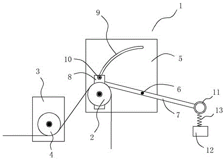
[0014] Embodiment one: if figure 1 As shown, a chemical fiber yarn tensioning mechanism includes an incoming wire wheel 2 installed on an incoming wire wheel seat 1 and an outgoing line wheel 4 installed on an outgoing line wheel seat 3. The outgoing line wheel 4 and the incoming line wheel 2 are located at the same vertical In the plane, and the outlet wheel 4 is located obliquely below the inlet wheel 2, the inlet wheel seat 1 includes an arc-shaped hole seat 5, a rotating shaft 6, a rotating rod 7 and a slider 8, wherein the rotating shaft 6 is arranged on the arc-shaped hole seat 5 Above, an arc-shaped strip hole 9 is provided on the arc-shaped hole seat 5, and the center position of the arc-shaped strip-shaped hole 9 coincides with the position of the rotating shaft 6, and the slider 8 is connected to the arc-shaped hole seat through a positioning bolt 10 In the arc-shaped strip hole 9 of 5, the wire feed wheel 2 is located on the slide block 8, the rotating rod 7 is loca...
Embodiment 2
[0017] Embodiment two: still as figure 1 As shown, on the basis of the structure of Embodiment 1, as a further preference, for the above-mentioned chemical fiber tensioning mechanism, a weight 12 is also connected to the handle 11 .
[0018] Correspondingly, for the above-mentioned chemical fiber filament tensioning mechanism, buffer gaskets (not shown in the figure) are respectively provided at the upper and lower ends of the arc-shaped strip hole 9 of the arc-shaped hole seat 5, and are located at The thickness of the buffer gasket at the upper end of the arc-shaped bar-shaped hole 9 is greater than the thickness of the buffer gasket at the lower end of the arc-shaped bar-shaped hole 9 . In addition, as a further preference, a spring 13 is further provided between the handle 11 and the weight 12 .
[0019] In this way, the positioning bolt 10 can always be kept in a loose state (that is, no need to be tightened again), and a constant and upward force is always applied to th...
PUM
 Abstract
Description
Claims
Application Information
 - R&D
- Intellectual Property
- Life Sciences
- Materials
- Tech Scout
- Unparalleled Data Quality
- Higher Quality Content
- 60% Fewer Hallucinations
Browse by: Latest US Patents, China's latest patents, Technical Efficacy Thesaurus, Application Domain, Technology Topic, Popular Technical Reports.
© 2025 PatSnap. All rights reserved.Legal|Privacy policy|Modern Slavery Act Transparency Statement|Sitemap|About US| Contact US: help@patsnap.com

