
Combined retaining structure and construction method thereof

A technology of retaining structure and construction method, which is applied in the direction of foundation structure engineering, underwater structures, excavation, etc., and can solve the problems of compaction of filled soil behind walls, large differential settlement of panels and reinforced soil, and small panel rigidity, etc. To meet the requirements of reducing the bearing capacity of the foundation and settlement control, homogenize and reduce the horizontal deformation of the wall, and prevent the filling from extrusion or local slump

Inactive Publication Date: 2015-12-16
HUAZHONG UNIV OF SCI & TECH
View PDF9 Cites 35 Cited by
  • Summary
  • Abstract
  • Description
  • Claims
  • Application Information

AI Technical Summary

Problems solved by technology

The disadvantages are: (1) It is not suitable for landslides, water erosion and other unfavorable geological areas; (2) The panel stiffness of traditional turn-up and modular reinforced earth retaining walls is small, and the single-stage wall height is generally below 10m If it is too high, it is easy to cause large wall deformation or overall instability, and at the same time, it is easy to cause a large-scale collapse due to local tie breakage; (3) Even if the overall cast-in-place reinforced concrete panel is used, the traditional process is to pour the panel first Refilling, at this time, it will be difficult to compact the filling soil behind the wall, and the settlement difference between the face plate and the reinforced soil is relatively large, and the reinforcement material is directly connected to the face plate, and it is easy to cause the filling soil compaction construction and the excessive foundation difference. connection failure due to subsidence

Method used


Image

  • Combined retaining structure and construction method thereof
  • Combined retaining structure and construction method thereof
  • Combined retaining structure and construction method thereof

Examples


Embodiment Construction

[0033] The present invention will be further described below in conjunction with accompanying drawings and examples of implementation.

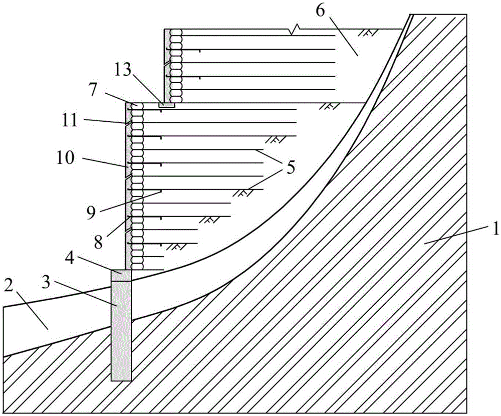
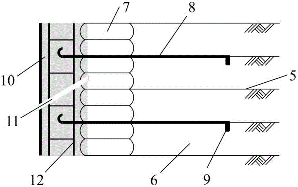
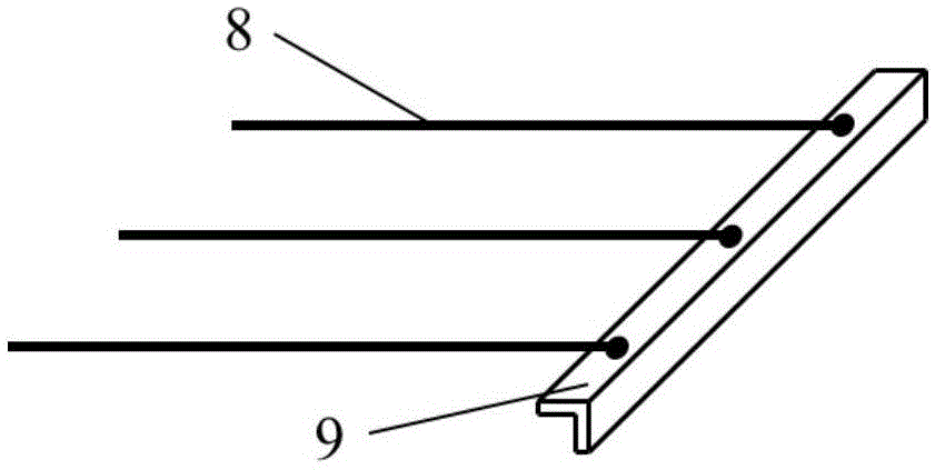
[0034] A combined retaining structure, such as Figure 1 ~ Figure 3 As shown, it includes anti-slide pile 3, connecting beam 4, reinforced soil retaining wall (composed of geogrid 5, filling soil 6 and bagged gravel 7), rigid panel (composed of cast-in-place concrete slab 10, drainage Holes 11 and reinforcement mesh 12 are jointly formed) and connecting member (comprising anchor reinforcement bar 8 and angle steel 9). The anti-slide pile 3 penetrates the covering soil layer 2 and is anchored in the stable stratum 1; the connecting beam 4 is located on the top of the anti-sliding pile 3, and the bottom of the beam is in contact with the covering soil layer 2; the reinforced soil retaining wall is a turn-up geogrid Reinforced earth retaining wall, the wall is made of bagged crushed stones, which can be constructed in stages; the rigid panel is...


PUM

PropertyMeasurementUnit
Spacingaaaaaaaaaa
Ultimate tensile strengthaaaaaaaaaa
Lengthaaaaaaaaaa

Abstract

The invention relates to a combined retaining structure and a construction method thereof. The combined retaining structure comprises anti-sliding piles, connecting beams, a ribbed soil retaining wall, rigid panels and connecting components. The anti-sliding piles penetrate a covering soil layer and are anchored in a stable stratum. The anti-sliding piles are arranged in parallel, and the connecting beams are arranged at the tops of the anti-sliding piles. The rigid panels are arranged at the tops of the connecting beams. The ribbed soil retaining wall is built behind the rigid panels. The connecting components are arranged between the rigid panels and the ribbed soil retaining wall and connected with the rigid panels and the ribbed soil retaining wall respectively. The combined retaining structure is high in adaptability to foundations and sites, higher in overall rigidity, good in stability, convenient to construct, large in building height, good in anti-seismic property and suitable for highfill projects on complex terrains of western mountainous areas.

Description

technical field [0001] The invention belongs to the field of slope stability support in geotechnical engineering, and relates to a combined retaining structure and a construction method thereof, in particular to a combined retaining structure suitable for high filling engineering on complex terrain in western mountainous areas and a construction method thereof. Background technique [0002] In recent years, with the large-scale construction of transportation infrastructure in western my country, a large number of high-filling projects on complex terrain in mountainous areas have appeared. Such high-filling projects often have the following characteristics: (1) The filling height is large, reaching several Tens to hundreds of meters, large deformation after construction; (2) Located on valleys, steep slopes and other terrains, the site is narrow, and it is difficult for large-scale construction machinery to enter the site; (3) The slope is steep, and the stability of the coveri...

Claims


Application Information

Patent Timeline
IPC IPC(8): E02D17/20E02D29/02
Inventor 郑俊杰曹文昭薛鹏鹏吕思祺郭震山
Owner HUAZHONG UNIV OF SCI & TECH
Features
  • Generate Ideas
  • Intellectual Property
  • Life Sciences
  • Materials
  • Tech Scout
  • Unparalleled Data Quality
  • Higher Quality Content
  • 60% Fewer Hallucinations
Learn More