Anti-streaking row-scanning control chip and anti-streaking LED display circuit

A control chip and anti-drag technology, applied to static indicators, instruments, etc., can solve the problems of high cost, complex wiring, poor LED dynamic screen effect, etc., to reduce application cost, simplify wiring difficulty, and improve display clarity Effect

Active Publication Date: 2015-12-16
SHENZHEN SUNMOON MICROELECTRONICS
View PDF13 Cites 11 Cited by
  • Summary
  • Abstract
  • Description
  • Claims
  • Application Information

AI Technical Summary

Problems solved by technology

[0006] The purpose of the embodiments of the present invention is to provide a method to solve the existing problems of poor effect of eliminating LED dynamic screen, high cost and complicated wiring.

Method used


Image

  • Anti-streaking row-scanning control chip and anti-streaking LED display circuit
  • Anti-streaking row-scanning control chip and anti-streaking LED display circuit
  • Anti-streaking row-scanning control chip and anti-streaking LED display circuit

Examples


Embodiment Construction

[0031] In order to make the object, technical solution and advantages of the present invention clearer, the present invention will be further described in detail below in conjunction with the accompanying drawings and embodiments. It should be understood that the specific embodiments described here are only used to explain the present invention, not to limit the present invention. In addition, the technical features involved in the various embodiments of the present invention described below can be combined with each other as long as they do not constitute a conflict with each other.

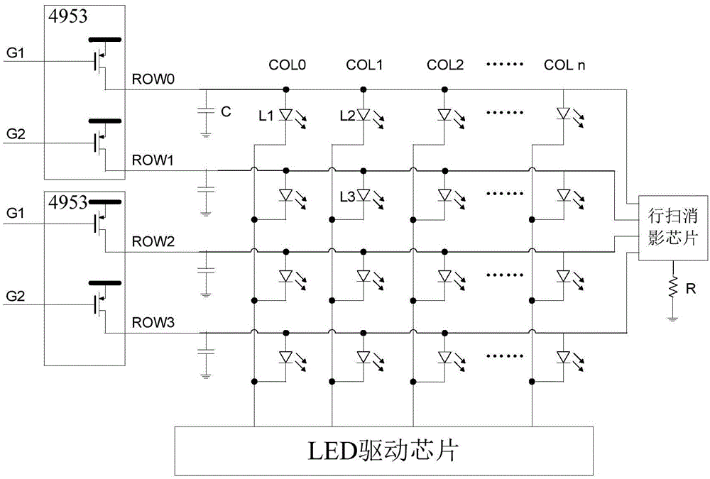
[0032] In the embodiment of the present invention, the shadow elimination function is integrated into the line scan control chip, and the shadow elimination processing is performed on the LED lines, or the LED line is eliminated through an external shadow elimination signal, which greatly reduces the wiring difficulty of the display unit board and application costs.

[0033] Figure 4 The inte...


PUM


Abstract

The invention is suitable for LED field and provides an anti-streaking row-scanning control chip and an anti-streaking LED display circuit, wherein the chip comprises a two-row-scanning enablement pin and a two-row-scanning control pin connected with an LED row line, a streaking enablement pin and an external streaking signal pin, a first switch tube and a second switch tube, and a streaking signal generation unit that is used to generate a row line streaking pulse controlling the row line discharge parasitic charge based on a row line enablement signal, a gating unit that is used for processing a row line shadow pulse and an external streaking signal, and for outputting the processed external streaking signal when the streaking mode enablement signal is the external input streaking signal state, and for outputting the processed row line streaking pulse when the streaking mode enablement signal is the internal generated streaking pulse state. The streaking function is integrated into the row-scanning control chip, or the LED row line is processed for streaking through an external streaking signal, therefore, the display screen wiring difficulty is reduced due to high integration and the application cost is reduced.

Description

technical field [0001] The invention belongs to the field of LEDs, in particular to an anti-smear line scan control chip and an anti-smear LED display circuit. Background technique [0002] Due to the LED display has many advantages such as low voltage, energy saving, and long service life, it has been widely used in various fields. According to the LED display scanning method, it can be divided into dynamic screen and static screen. The static screen is the scanning line of each scan line. It is turned on at the same time, and each LED light is controlled by a different driver chip, which requires a lot of driver chips to control; the dynamic screen only displays a certain line at a certain time, and then displays the next line at the next time until all lines are displayed. And then display the first row, and so on, cycle display, and display the whole picture, which can greatly reduce the number of driver chips and reduce the cost. [0003] The scanning method of the dyn...

Claims


Application Information

Patent Timeline
Patent Type & Authority Applications(China)
IPC IPC(8): G09G3/32
Inventor 李照华杜思葵吕苏谊石磊
Owner SHENZHEN SUNMOON MICROELECTRONICS
Why Eureka
Try Eureka