Liquid crystal panel for 3D display, driving method and pixel optimization method thereof

a technology of liquid crystal panel and 3d display, which is applied in the direction of static indicating device, non-linear optics, instruments, etc., can solve the problems of increasing production cost and difficult process of fpr film, and achieve the effect of improving display definition and reducing 3d display cos

Active Publication Date: 2018-12-06
TCL CHINA STAR OPTOELECTRONICS TECH CO LTD
View PDF1 Cites 3 Cited by
  • Summary
  • Abstract
  • Description
  • Claims
  • Application Information

AI Technical Summary

Benefits of technology

[0005]One of the technical problems to be solved by the present disclosure is to provide a 3D display solution capable of reducing the 3D display cost while improving the display definition.
[0015]Compared with the prior art, one or more embodiments in the above solution may have the following advantages or beneficial effects:
[0016]By using the FPR film covering two lines of sub-pixel units to manufacture a liquid crystal panel, and combining the 2Line-by-2Line driving method and the SPR algorithm to perform picture display on the liquid crystal panel, it is possible to reduce the production cost of the 3D display device, increase the resolution and improve the displayed picture quality.

Problems solved by technology

High definition and low cost are a pair of contradictory factors because in the prior art, with the increase in the resolution of a 3D display device, the process of the FPR film becomes more and more difficult, which will inevitably lead to an increased production cost.

Method used


Image

  • Liquid crystal panel for 3D display, driving method and pixel optimization method thereof
  • Liquid crystal panel for 3D display, driving method and pixel optimization method thereof
  • Liquid crystal panel for 3D display, driving method and pixel optimization method thereof

Examples


first embodiment

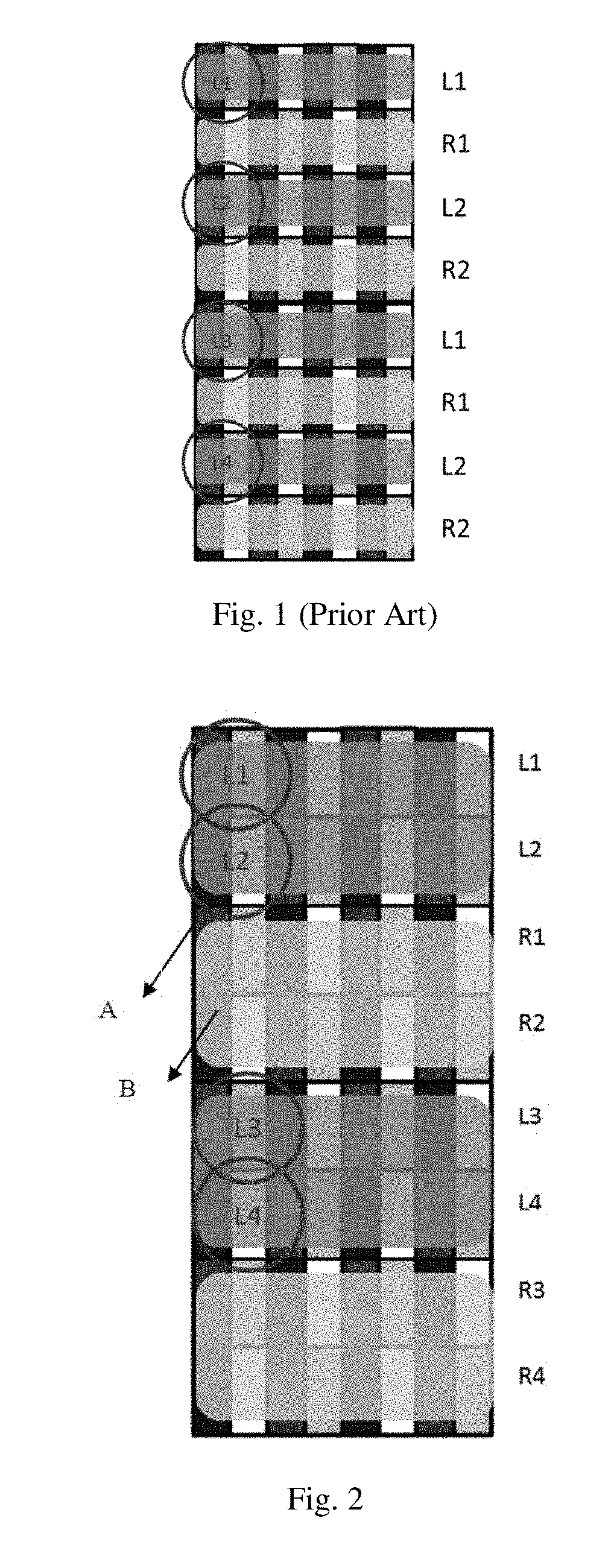
[0030]FIG. 2 is a structural schematic diagram of a liquid crystal panel for 3D display according to the first embodiment of the present disclosure. As shown in FIG. 2, the liquid crystal panel comprises a display panel A and an FPR film B attached to a surface of the display panel.

[0031]The display panel A is provided with orthogonally arranged multi-line, multi-column sub-pixel units, and the sub-pixel units receive the image data through scanning lines and data lines to display the pictures.

[0032]The FPR film B is also divided into first areas for left-eye picture display and second areas for right-eye picture display. As shown in FIG. 2, the dark stripes with darker gray represent the first areas and the dark stripes with lighter gray represent the second areas; the first areas and the second areas are arranged alternately in a direction parallel to lines of the sub-pixel units, and the first areas and the second areas arranged alternately each cover two lines of sub-pixel units...

second embodiment

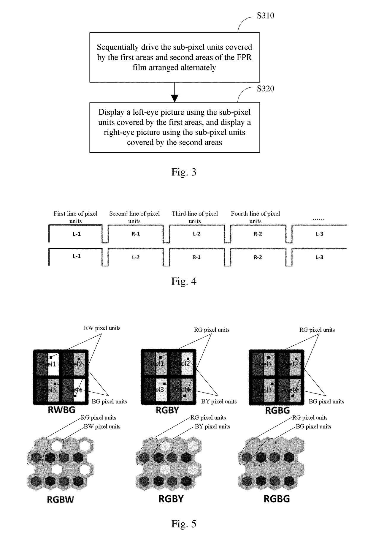
[0034]FIG. 3 is a flow schematic diagram of a driving method for driving a liquid crystal panel for 3D display according to the second embodiment of the present disclosure. FIG. 4 is a data transmission sequence diagram of a driving method for driving a liquid crystal panel for 3D display according to the second embodiment of the present disclosure, and the driving method comprises the following steps.

[0035]In Step S310, the sub-pixel units covered by the first areas and the second areas of the FPR film arranged alternately are sequentially driven.

[0036]In Step S320, left-eye pictures are displayed using the sub-pixel units covered by the first areas, and right-eye pictures are displayed using the sub-pixel units covered by the second areas.

[0037]Specifically, with reference to FIG. 2 and FIG. 4, the scanning lines in respective lines are driven in an order from top to bottom for picture display; when driving the first areas covering the first line of sub-pixel units and the second ...

third embodiment

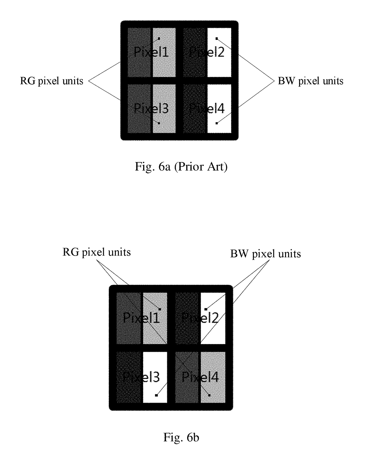
[0044]Further, when the display panel with the pixel structure presenting a PenTile arrangement is employed as the liquid crystal panel in the embodiment of the present disclosure, it is possible to improve its resolution by a virtual pixel compensation means.

[0045]PenTile is a kind of pixel arrangement mode developed by Samsung Corp, and it was firstly applied to the mobile phone of an OLED material. Different from a single sub-pixel unit in the standard RGB arrangement, the sub-pixel unit in the standard RGB arrangement consists of three sub-pixels of red, green and blue, while there are only two kinds of sub-pixel units of PenTile and each kind of sub-pixel unit contains two colors.

[0046]As shown in FIG. 5, several examples of the PenTile arrangement mode are provided, in which two sub-pixel units of the RWBG are Red-White (RW) and Blue-Green (BG); Pixel 1 and Pixel 4 in this figure are RW pixel units; Pixel 2 and

[0047]Pixel 3 are BG pixel units; and the two kinds of pixel units ...


PUM

PropertyMeasurementUnit
RGaaaaaaaaaa
RGaaaaaaaaaa
areasaaaaaaaaaa

Abstract

Disclosed is a liquid crystal panel for 3D display, a driving method and a pixel optimization method thereof. The liquid crystal panel includes a display panel and an FPR film attached to a surface of the display panel. The FPR film is divided into first areas and second areas, the first areas and the second areas being arranged alternately in a direction parallel to lines of the sub-pixel units of the display panel, and each covering two lines of sub-pixel units. The liquid crystal panel can reduce the production cost of the 3D display device and improve the resolution.

Description

CROSS-REFERENCE TO RELATED APPLICATIONS[0001]This application claims the priority of Chinese patent application CN201610791990.4, entitled “Liquid Crystal Panel for 3D Display, Driving Method and Pixel Optimization Method Thereof” and filed on Aug. 31, 2016, the entirety of which is incorporated herein by reference.FIELD OF THE INVENTION[0002]The present disclosure relates to the field of liquid crystal display devices, and in particular, to a liquid crystal panel for 3D display, a driving method and a pixel optimization method thereof.BACKGROUND OF THE INVENTION[0003]With the development of 3D display technology, the 3D display device has gradually become a general requirement and configuration. As a universal implementation mode of 3D, users of an FPR (Film-type Patterned Retarder) liquid crystal display device have put forward higher requirements for 3D applications, and so developers are committed to producing display products with high definition and low cost to occupy the mark...

Claims


Application Information

Patent Timeline
Patent Type & Authority Applications(United States)
IPC IPC(8): G09G3/00G02F1/13363G09G3/36
CPCG09G3/003G02F1/13363G09G3/3611G02F2201/52G09G2340/0457G02F1/13306G02F1/133528G09G3/3607G02F1/133G02F1/1335
Inventor JIN, YUFENGSYU, SHEN SIAN
Owner TCL CHINA STAR OPTOELECTRONICS TECH CO LTD
Why Eureka
Try Eureka