Ram-type splitting system

A stamping and slitting technology, which is applied in the manufacture of electrical components, semiconductor/solid-state devices, circuits, etc., can solve the problems of long time consumption, reduce the efficiency of grain splitting, and low machine productivity, so as to improve the yield of slitting products, The effect of improving slivers production efficiency

Active Publication Date: 2015-12-16
EPITOP PHOTOELECTRIC TECH
View PDF4 Cites 6 Cited by
  • Summary
  • Abstract
  • Description
  • Claims
  • Application Information

AI Technical Summary

Problems solved by technology

However, the splitting tool of the splitting device in the current splitting machine mainly uses a cuboid, which can only split one row of grains in the X direction or Y direction at a time, which consumes a long time and the machine capacity is low.
[0004] Therefore, in the process of dividing the COW wafer into independent individual grains by using the current splitter, since the splitting tool of the splitter in the splitter can only split a row of grains in the X direction or the Y direction at a time, time consumption Longer, reducing the efficiency of die splitting from COW wafers

Method used


Image

  • Ram-type splitting system
  • Ram-type splitting system
  • Ram-type splitting system

Examples


Embodiment Construction

[0023] In order to make the purpose, technical solutions and advantages of the embodiments of the present invention clearer, the technical solutions in the embodiments of the present invention will be clearly and completely described below in conjunction with the drawings in the embodiments of the present invention. Obviously, the described embodiments It is a part of embodiments of the present invention, but not all embodiments. Based on the embodiments of the present invention, all other embodiments obtained by persons of ordinary skill in the art without creative efforts fall within the protection scope of the present invention.

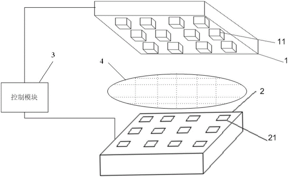
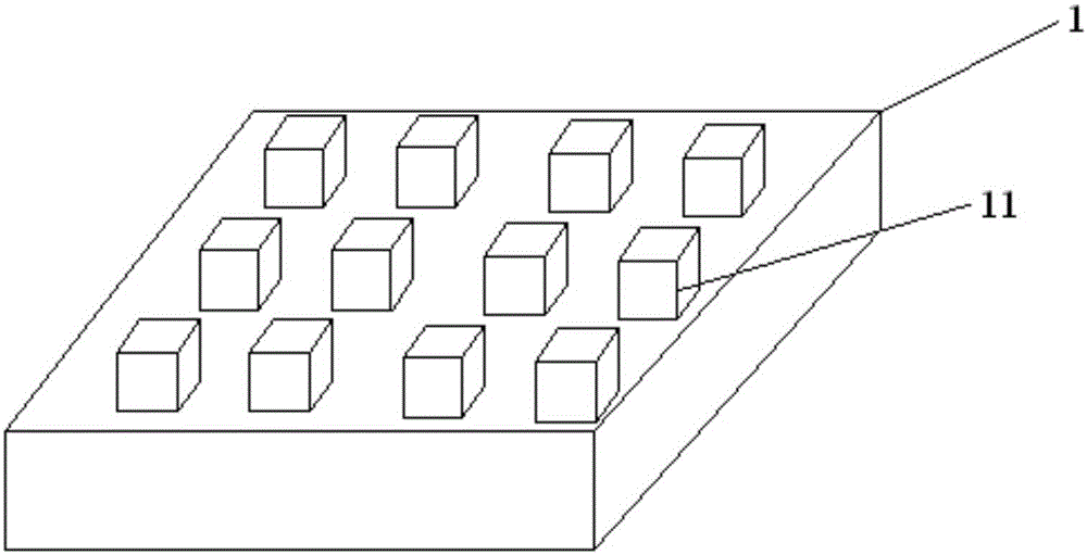
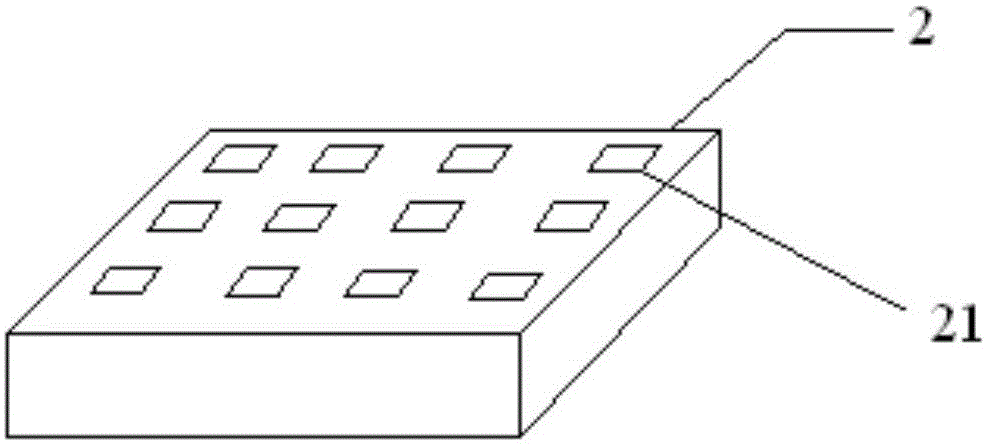
[0024] figure 1 It is a schematic structural diagram of the stamping split system provided by the embodiment of the present invention. Such as figure 1 As shown, the stamping split system provided by the embodiment of the present invention includes: an impact plate 1 , a groove plate 2 and a control module 3 .

[0025] The impact plate 1 is equ...


PUM


Abstract

The invention provides a ram-type splitting system, which comprises an impact plate, a groove plate and a control module, wherein at least one impact head for impacting to-be-divided wafers is arranged on the impact plate; the impact heads are evenly distributed on the impact plate; at least one groove matched with the impact heads is formed in the groove plate; the grooves are evenly distributed in the groove plate; the number of the impact heads and the number of the grooves are the same as that of crystal particles on the to-be-divided wafers; and the control module is used for controlling the impact heads on the impact plate to impact the to-be-divided wafers on the groove plate and controlling the impact heads to impact the to-be-divided wafers into the grooves in the groove plate. According to the ram-type splitting system provided by the invention, the splitting production efficiency can be improved, so that the split product yield is improved.

Description

technical field [0001] The invention relates to the field of light-emitting diode manufacturing, in particular to a stamping split system. Background technique [0002] In the production process of light-emitting diode (Light Emitting Diode, referred to as LED) chips, the splitting process is a key step related to the final yield of the finished product. The connected dies are separated into individual entities, and the connected dies are separated from each other to form core dies. [0003] At present, in the process of dividing the COW wafer into independent individual grains, the splitting device in the splitter is mainly used to exert a certain impact force on the COW wafer between the grain and the cutting line of the grain, and the COW The wafer is cleaved into individual dies. However, the splitting tool of the splitting device in the current splitting machine mainly uses a cuboid shape, which can only split one row of grains in the X direction or Y direction at a t...

Claims


Application Information

Patent Timeline
Patent Type & Authority Applications(China)
IPC IPC(8): H01L21/78H01L21/67
CPCH01L21/67092H01L21/78
Inventor 段中红韩晓翠曹喜平康建梁旭东
Owner EPITOP PHOTOELECTRIC TECH
Why Eureka
Try Eureka