
A tooth scaler handle

A dental scaler and handle technology, applied in the field of medical machinery, can solve the problems of short circuit, inconvenient operation, and high operator requirements, and achieve the effects of safe use, good teeth cleaning effect, and convenient operation.

Inactive Publication Date: 2017-04-26
张世玲
View PDF5 Cites 0 Cited by
  • Summary
  • Abstract
  • Description
  • Claims
  • Application Information

AI Technical Summary

Problems solved by technology

[0003] The handle of the ultrasonic dental scaler is the core component of the whole machine, and there are the following problems in use: 1) It is equipped with a circuit and a waterway at the same time, and it is easy to cause waterway leakage during use, which is likely to cause a short circuit; 2) It also has the problem of inconvenient operation. Because the operator pinches the handle with his hand, the hand vibrates together with the handle, and the strength of hand pinching affects the vibration effect. To achieve a good tooth cleaning effect, the requirements for the operator are too high; 3) In order to spray and wash, the existing working head adopts a hollow structure, and the horn, the inside of the handle and the tail wire sleeve of the handle all need to be connected with the working head. The waterway connected to the head, especially in the tail sleeve of the handle, the water pipe and the cable are set together, which makes the structure of the whole handle more complicated, and there are too many pipe connection parts in the handle, which is more likely to cause leakage; 4) The light in the mouth is dark , the line of sight is not clear during the operation, and it is necessary to use auxiliary tools such as a flashlight, which makes the operation very time-consuming and laborious

Method used


Image

  • A tooth scaler handle
  • A tooth scaler handle
  • A tooth scaler handle

Examples


Embodiment Construction

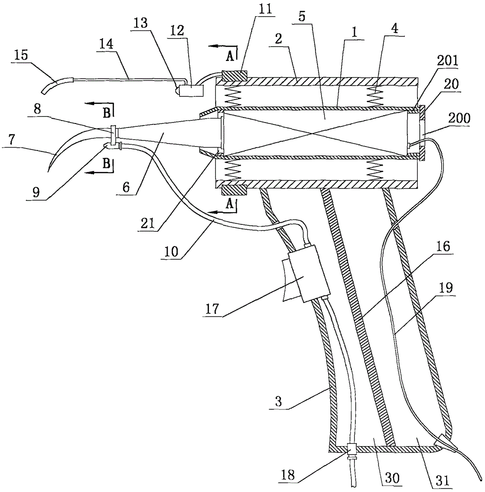
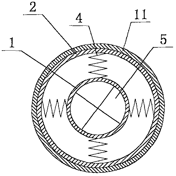
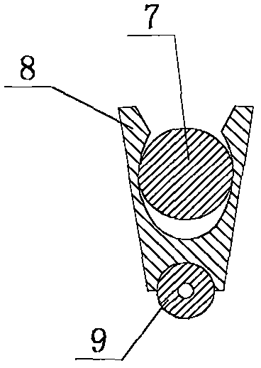
[0016] With reference to the accompanying drawings, the scaler handle of the present invention includes an inner cylinder 1 and an outer cylinder 2 sleeved outside the inner cylinder 1, the bottom of the outer cylinder 2 is connected with a handle 3, and the outer wall of the inner cylinder 1 is connected to the outer wall of the inner cylinder 1. A plurality of supporting springs 4 are connected between the inner walls of the outer cylinder 2, and an ultrasonic transducer 5 is fixedly installed in the inner cylinder 1, and the front end of the ultrasonic transducer 5 is connected to the horn 6, and the front end of the horn 6 extends Out of the inner cylinder 1 and connected to the working head 7 at the front end of the horn 6; the rear of the working head 7 is fitted with a water spray nozzle 9 with an opening facing forward through an elastic clip 8, and the rear end of the water spray nozzle 9 A water pipe 10 is connected; a rotating sleeve 11 is set on the front end of the...


PUM


Abstract

The invention relates to a handle of a tooth cleaning machine. The handle comprises an inner barrel and an outer barrel, wherein the inner barrel is sleeved with the outer barrel. A handheld handle body is connected to the bottom of the outer barrel, multiple supporting springs are connected between the outer wall of the inner barrel and the inner wall of the outer barrel, an ultrasonic transducer is fixedly installed inside the inner barrel, an amplitude-change pole is connected to the front end of the ultrasonic transducer, the front end of the amplitude-change pole extends out of the inner barrel, and a working head is connected to the front end of the amplitude-change pole. A water spraying nozzle with a forward opening is clamped to the rear of the working head through an elastic clamp, and a water pipe is connected to the rear end of the water spraying nozzle. The front end of the outer barrel is sleeved with a rotating sleeve, and a lighting mechanism is installed on the rotating sleeve. The handle has the advantages of achieving a lighting function and being safe to use, convenient and rapid to operate and good in tooth-cleaning effect.

Description

technical field [0001] The invention relates to the field of medical machinery, in particular to a special handle for dental scalers. Background technique [0002] Ultrasonic tooth scaler uses the high-frequency, high-energy vibration generated by ultrasonic waves to crush and fall off the calculus and tooth stains on the surface of the teeth through the smooth working head of the ultrasonic scaler. The working head is generally a hollow structure, which can be connected to the water pipe Road, so that the dirt that has fallen off can be washed to achieve the purpose of cleaning the teeth. Ultrasonic scalers generally include a power supply, a host, a handle and a foot switch. An ultrasonic generator is installed in the host, the working head is installed on the horn at the front end of the handle, and an ultrasonic wave connected to the ultrasonic generator through a cable is installed in the handle. Transducer, the ultrasonic transducer converts the high-frequency electri...

Claims


Application Information

Patent Timeline
Patent Type & Authority Patents(China)
IPC IPC(8): A61C17/20F21V7/04F21V33/00A61B1/247
Inventor 张世玲郝艳芹
Owner 张世玲
Learn More