Heating cartridge for a juice concentration device
A concentration device and heating cartridge technology, which is applied in the direction of making medicines into special physical or ingestible devices, evaporator accessories, evaporation, etc., can solve the problems of easy adhesion on the inner wall of the equipment, slow juice circulation, equipment blockage, etc. problems, to achieve the effect of improving production efficiency and finished product quality, reducing the degree of adhesion, and slowing down clogging
- Summary
- Abstract
- Description
- Claims
- Application Information
AI Technical Summary
Problems solved by technology
Method used
Image

Examples
Embodiment 1
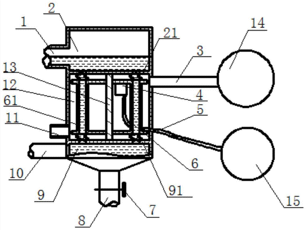
[0019] Such as figure 1 , the present invention proposes a heating cartridge for a juice concentration device, comprising an upper chamber 2, a heating chamber 12, and a lower chamber 9, the side wall of the upper chamber 2 is provided with a discharge pipe 1; the upper part of the side wall of the heating chamber 12 is provided with There is a steam pipe 3 connected to the steam source 14, a steam discharge pipe 11 is provided at the bottom of the side wall of the heating chamber 12, and an evaporating tube bundle 6 is arranged inside the heating chamber 12, and the evaporating tube bundle 6 is sealed softly with the upper chamber 2 and the lower chamber 9. The evaporating tube bundle 6 is connected with the vibrator 4. A vertical intermediate shaft 13 is arranged in the middle of the heating chamber 12, and the intermediate shaft 13 runs through the evaporating tube bundle 6; A finished product outlet 8 is provided at the bottom of the chamber 9 .
[0020] The intermediate ...
Embodiment 2
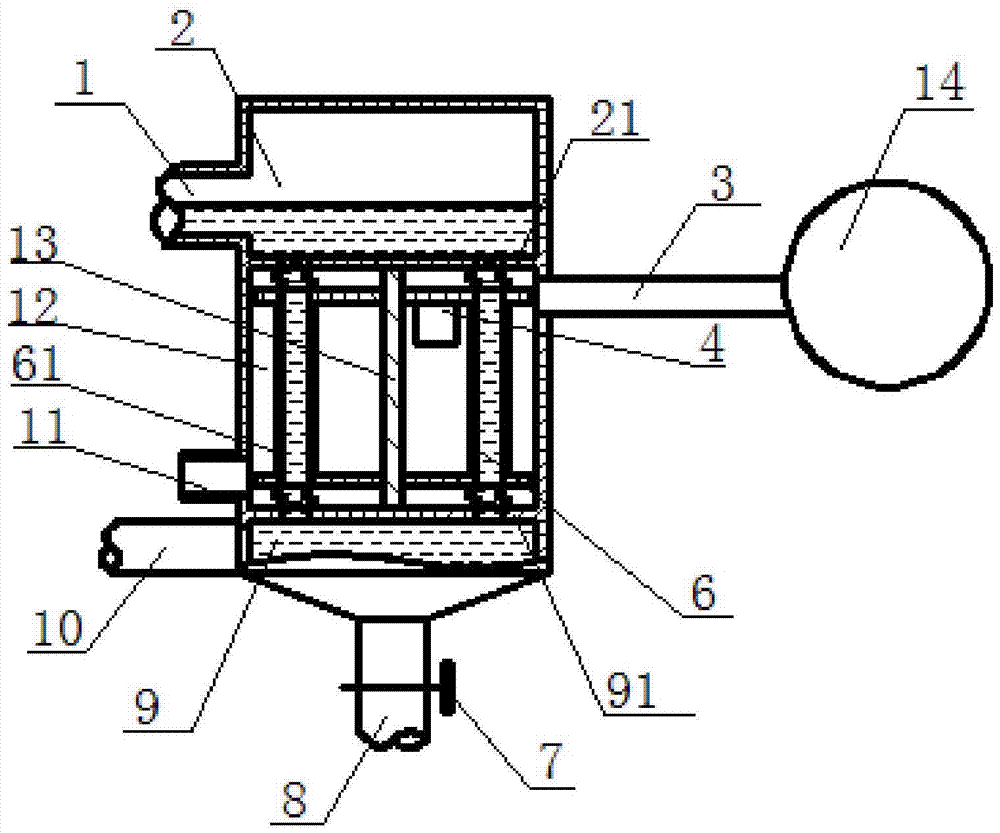
[0025] Such as figure 2 , the present invention proposes a heating cartridge for a juice concentration device, comprising an upper chamber 2, a heating chamber 12, and a lower chamber 9, the side wall of the upper chamber 2 is provided with a discharge pipe 1; the upper part of the side wall of the heating chamber 12 is provided with There is a steam pipe 3 connected to the steam source 14, a steam discharge pipe 11 is provided at the bottom of the side wall of the heating chamber 12, and an evaporating tube bundle 6 is arranged inside the heating chamber 12, and the evaporating tube bundle 6 is sealed softly with the upper chamber 2 and the lower chamber 9. The evaporating tube bundle 6 is connected with the vibrator 4. A vertical intermediate shaft 13 is arranged in the middle of the heating chamber 12, and the intermediate shaft 13 runs through the evaporating tube bundle 6; A finished product outlet 8 is provided at the bottom of the chamber 9 .
[0026] The intermediate...
PUM
 Abstract
Description
Claims
Application Information