Experiment model structure related to adhering feature between concrete and steel pile casting

An experimental model, the technology of steel casing, applied in the direction of measuring devices, instruments, mechanical devices, etc., to achieve the effect of uniform force and reduce test errors

Pending Publication Date: 2018-04-27
HEFEI UNIV OF TECH
View PDF3 Cites 0 Cited by
  • Summary
  • Abstract
  • Description
  • Claims
  • Application Information

AI Technical Summary

Problems solved by technology

[0004] The purpose of the present invention is to solve the value problem of the bonding strength between concrete and steel casing, and provide a kind of experimental model structure about the bonding characteristics of concrete and steel casing

Method used


Image

  • Experiment model structure related to adhering feature between concrete and steel pile casting
  • Experiment model structure related to adhering feature between concrete and steel pile casting
  • Experiment model structure related to adhering feature between concrete and steel pile casting

Examples


Embodiment 1

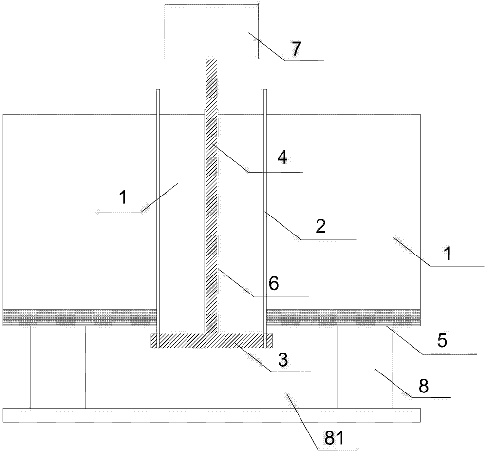
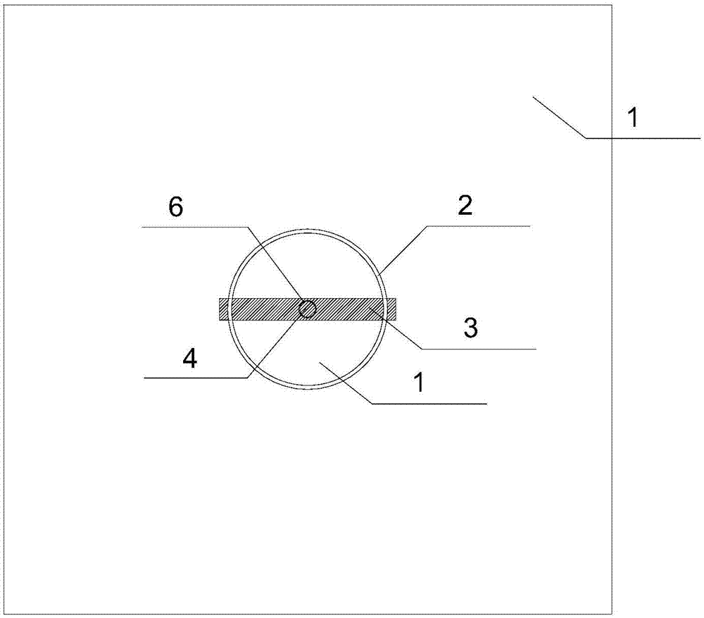
[0034] Such as Figure 1-2 As shown, an experimental model structure about the bonding characteristics of concrete and steel casing, including steel casing 2, loading module, reinforcement plate 5, said loading module includes beam 3 and loading column 4, and said steel casing 2 Concrete 1 is poured inside and outside respectively, and the loading module is connected with the steel casing (2), and the loading module provides the force to stretch the steel casing 2 to separate the steel casing 2 from the concrete 1. The steel casing 2 is provided with a hole, the beam 3 passes through the hole on the steel casing 2 and is fixed on the steel casing 2 , and one end of the loading column 4 is connected to the beam 3 .

[0035] In this embodiment, the level of the beam 3 on the steel casing 2 is lower than the level of the lower surface of the concrete 1 , and the other end of the steel casing 2 is higher than the level of the upper surface of the concrete 1 . The reinforcing plat...

Embodiment 2

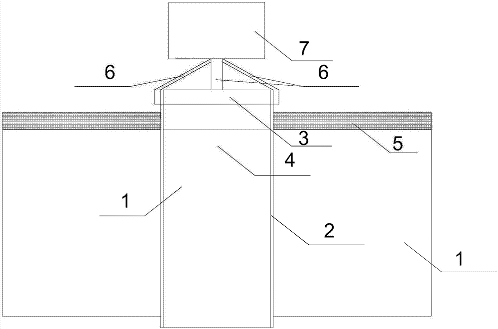
[0042] Such as Figure 3-4 As shown, an experimental model structure about the bonding characteristics of concrete and steel casings includes steel casings 2, beams 3, loading columns 4, and reinforcement plates 5, and the inner and outer walls of the steel casing 2 are respectively Concrete 1 is poured, and the side wall of the lower part of the steel casing 2 is provided with a hole through which the beam 3 passes. One end of the loading column 4 is fixed on the cross bar, and the other end is loaded with the tensile steel casing 2 to make it detached The force of the concrete 1, both ends of the steel casing 2 are located outside the concrete 1, and the beam 3 on the steel casing 2 is also located outside the concrete 1.

[0043]In this embodiment, the horizontal height of the beam 3 is higher than that of the concrete 1, and the reinforcing plate 5 is provided with a through hole through which the steel casing 2 passes, and the reinforcing plate 5 is arranged on the concre...


PUM

PropertyMeasurementUnit
thicknessaaaaaaaaaa
thicknessaaaaaaaaaa
thicknessaaaaaaaaaa

Abstract

The invention discloses an experiment model structure related to an adhering feature between concrete and a steel pile casting. The experiment model structure comprises the steel pile casting and a loading module and is characterized in that the concrete is poured inside and outside the steel pile casting, the loading module is connected with the steel pile casting, the loading module provides pulling force for pulling the steel pile casting away from the concrete, and two ends of the steel pile casting are located outside the concrete. The experiment module structure has the advantages that force is applied to a loading column and transmitted to the steel pile casting to allow the steel pile casting to be in a pulled state instead of a pressed state, and accordingly data inaccuracy causedby steel pile casting deformation due to excessively large pressure is avoided; two ends of the steel pile casting are located outside the concrete to prevent adhering face change after relative displacement between the steel pile casting and the concrete occurs.

Description

technical field [0001] The invention relates to the field of architectural experimental models, in particular to an experimental model structure related to the bonding properties of concrete and steel casings. Background technique [0002] In the structural design of deep-water cofferdams, the greater the bonding force between concrete and steel casings, the smaller the required concrete thickness, so that the structures such as brackets in the cofferdams can also be reduced accordingly. Therefore, the bond stress between concrete and steel casing has a great influence on the design of the entire cofferdam. [0003] At present, traditional empirical data are mostly used for the value of the bonding stress between the concrete and the steel casing of the cap bottom seal. There are very few studies on this issue at home and abroad, the test results of various units are quite different, the test data is also small, there is no uniform standard for the value, and the versatilit...

Claims


Application Information

Patent Timeline
Patent Type & Authority Applications(China)
IPC IPC(8): G01N19/04
CPCG01N19/04
Inventor 姚华彦张子涵方少文朱大勇戴良军
Owner HEFEI UNIV OF TECH
Why Eureka
Try Eureka