Plate limiting device

A limit device and plate technology, which is applied in the field of mechanical processing, can solve the problems of deviation in the conveying process of the plate and affect the continuous dust removal of the plate, and achieve the effects of facilitating adjustment, preventing movement, and reducing wear

Inactive Publication Date: 2015-12-23
成都佰世成科技有限公司
View PDF0 Cites 5 Cited by
  • Summary
  • Abstract
  • Description
  • Claims
  • Application Information

AI Technical Summary

Problems solved by technology

At present, the dust removal device of the board relies on the conveying mechanism to realize the board passing through the dust removal mechanism step by step, effectively realizing the comprehensive dust removal of the board, but because there is no limit mechanism, the board is easy to shift during the conveying process, which affects the continuous dust removal of the board

Method used


Image

  • Plate limiting device
  • Plate limiting device
  • Plate limiting device

Examples


Embodiment Construction

[0014] The present invention will be further described in detail below in conjunction with the accompanying drawings and examples. The following examples are explanations of the present invention and the present invention is not limited to the following examples.

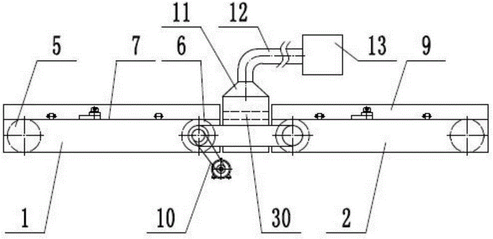
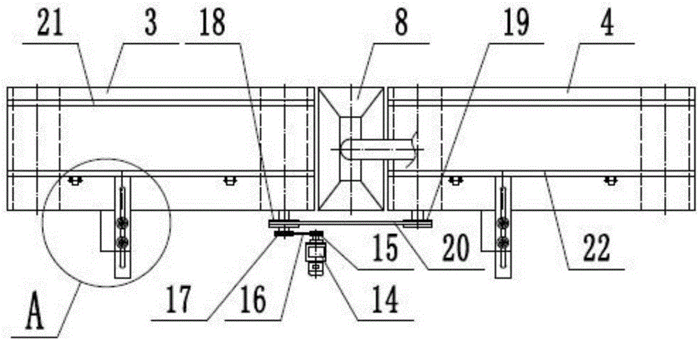
[0015] like figure 1 , figure 2 and image 3 As shown, a plate limit device includes a frame 1, a conveying mechanism 2, a dust removal mechanism 8, a limit mechanism 9, and a driving mechanism 10. The driving mechanism 10 realizes the continuous movement of the conveying mechanism 2, and the conveying mechanism 2 realizes the plate. The continuous conveying ensures that the plates pass through the dust removal mechanism 8 step by step. The limit mechanism 9 ensures that the plates are transported smoothly and does not move. The dust removal mechanism 8 realizes the comprehensive dust removal of the plates. The conveying mechanism 2 includes a front conveying assembly 3 and a rear conveying assembly 4, and the fr...


PUM


Abstract

The invention provides a plate limiting device and belongs to the technical field of machining. The plate limiting device comprises a conveying mechanism, a dust removal mechanism and a limiting mechanism. The dust removal mechanism is arranged between a front conveying assembly and a rear conveying assembly. A plate passage is arranged in a dust removal box of the dust removal mechanism. One end of a dust suction pipe is connected with the upper end of the dust removal box. The other end of the dust suction pipe is connected with a dust remover. A fixed limiting plate of the limiting mechanism is fixedly installed on a rack and located on the upper side of a conveyer belt. An adjusting plate is arranged on the outer side of a movable limiting plate vertically. The adjusting plate is provided with an adjusting U-shaped groove. A fixing support seat is fixedly arranged on the rack and located below the adjusting plate. A lock screw penetrates through the adjusting U-shaped groove to be in threaded connection with the fixing support seat. A roll wheel support seat is arranged below the movable limiting plate. A support roll wheel is arranged on the roll wheel support seat rotationally. The axis direction of the support roll wheel is perpendicular to the direction of the adjusting U-shaped groove. The plate limiting device can limit plates with various widths, and it is ensure that the plates do not shift in the conveying process.

Description

technical field [0001] The invention relates to the technical field of mechanical processing, in particular to a plate limiting device. Background technique [0002] Panels are usually manufactured as flat rectangular building material panels of standard sizes for use as wall, ceiling or floor elements. It also refers to forged, rolled or cast metal plates. Divided into thin plate, medium plate, thick plate, extra thick plate, usually made into flat rectangular building material plates of standard size. The shape of the plate product is flat, the ratio of width to thickness is large, and the surface area per unit volume is also large. This shape feature brings its characteristics in use: (1) The surface area is large, so the ability to contain and cover is strong. It is used in chemical industry, containers, construction, and metal products. (2) Can be arbitrarily cut, bent, stamped, welded, and made into various product components. It is flexible and convenient to use, an...

Claims


Application Information

Patent Timeline
Patent Type & Authority Applications(China)
IPC IPC(8): B08B13/00B65G21/20B65G21/22
CPCB08B13/00B65G21/2063B65G21/22
Inventor 樊世跃
Owner 成都佰世成科技有限公司
Why Eureka
Try Eureka