Hydraulic bending straightener

A straightening and hydraulic technology, which is applied in the field of hydraulic machinery, can solve the problems of heavy bending machines and cannot meet the needs of field operations, and achieve the effect of convenient and quick use

Inactive Publication Date: 2015-12-23
HANGZHOU ZHONGDUO FIRE FIGHTING SCI & TECH
View PDF7 Cites 6 Cited by
  • Summary
  • Abstract
  • Description
  • Claims
  • Application Information

AI Technical Summary

Problems solved by technology

Due to the use of electromagnetic force clamping, the pressure plate can be made into a variety of workpiece requirements, and workpieces with side walls can be processed, but the existing bending machines are relatively heavy and cannot meet field operations

Method used


Image

  • Hydraulic bending straightener
  • Hydraulic bending straightener
  • Hydraulic bending straightener

Examples


Embodiment

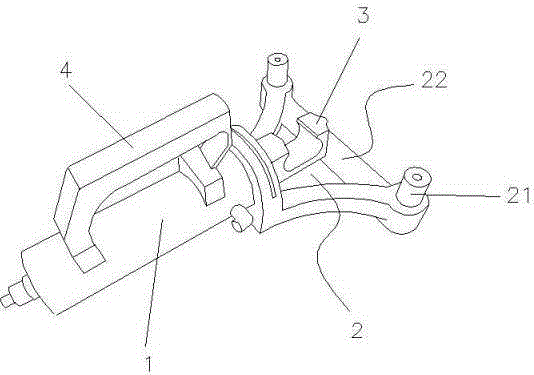
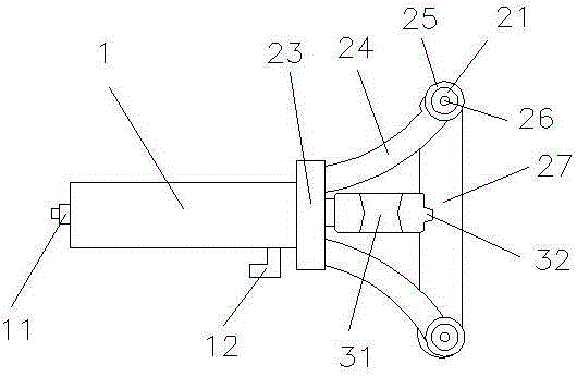
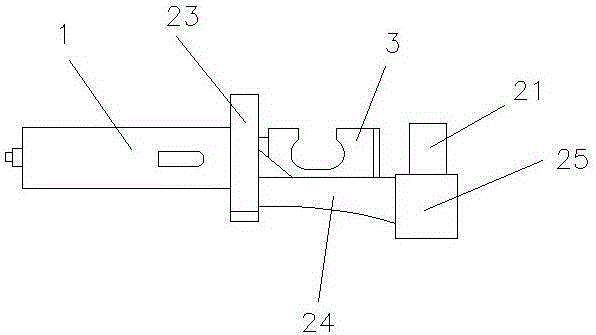
[0020] Embodiment: hydraulic bending straightener (see attached figure 1 , 2 , 3), including a hydraulic cylinder 1 and a bending assembly 2, the hydraulic cylinder 1 is fixedly connected to the bending assembly 2, the bending assembly 2 includes a bending frame 22 and a bending head 3, the bending The elbow 3 is fixedly connected with the hydraulic cylinder 2, the bending column 21 is arranged on the bending frame 22, the bending column 21 is fixedly connected with the bending frame 22, and the end of the bending head 3 is set Bending ribs 32, the bending ribs 32 are fixedly connected to the bending head 3, the bending groove 31 is set on the bending head 3, and the bending grooves 31 are arc-shaped on both sides Groove, the bending frame 22 includes a connecting seat 23 and a bending seat 25, a bending rod 24 is arranged between the bending seat 25 and the connecting seat 23, and one end of the bending rod 24 is connected to the bending The seat 25 is fixedly connected, th...


PUM


Abstract

The invention discloses a hydraulic bending straightener which comprises a hydraulic cylinder and a bending assembly. The hydraulic cylinder is fixedly connected with the bending assembly. The bending assembly comprises a bending frame and a bending head. The bending head is fixedly connected with the hydraulic cylinder. The bending frame is provided with bending columns. The bending columns are fixedly connected with the bending frame. According to the hydraulic bending straightener, a power is supplied to the bending head through the hydraulic cylinder. The bending head, the bending frame and the bending columns on the bending frame cooperate for bending an article which requires bending, thereby facilitating field operation, facilitating bending at a random angle and a random height, and realizing convenient and quick use.

Description

technical field [0001] The invention relates to the field of hydraulic machinery, and more specifically, the invention relates to a hydraulic bending and straightening device. Background technique [0002] At present, a bending machine is a machine that can bend thin plates. Its structure mainly includes a bracket, a workbench and a clamping plate. The workbench is placed on the bracket. The worktable is composed of a base and a pressure plate. The tight plates are connected, the base is composed of a seat shell, a coil and a cover plate, the coil is placed in the depression of the seat shell, and the top of the depression is covered with a cover plate. When in use, the wire is energized to the coil, and after energization, an attractive force is generated on the pressure plate, so as to realize the clamping of the thin plate between the pressure plate and the base. Due to the use of electromagnetic force clamping, the pressure plate can be made into various workpiece requi...

Claims


Application Information

Patent Timeline
Patent Type & Authority Applications(China)
IPC IPC(8): B21D5/04
CPCB21D5/04
Inventor 王俊
Owner HANGZHOU ZHONGDUO FIRE FIGHTING SCI & TECH
Why Eureka
Try Eureka