Die for continuously producing parts of automobile partition plate

A technology for partitions and parts, which is applied in the field of molds for continuous production of automobile partition parts, can solve problems such as potential safety hazards and parts quality problems, and achieve the effects of long service life, reduced damage and loss, and convenient maintenance

Inactive Publication Date: 2015-12-23
SHANGHAI ZHONGDA AUTO PARTS
6 Cites 0 Cited by

AI-Extracted Technical Summary

Problems solved by technology

There are safety hazards in the process of personnel operation, and...

Method used

Upper mold group comprises upper mold base 4 and the binder plate 5, punch and upper mold trimming cutter block that are fixed on upper mold base 4 lower surfaces, binder plate 5 is connected in the center of upper mold trimming cutter block In the lower part, the punch is arranged in the middle part of ...

Abstract

The invention relates to a die for continuously producing parts of an automobile partition plate. The die comprises an upper die set and a lower die set which are mutually matched, wherein the relative positions and distance between the upper die set and the lower die set are controlled through guide pillars; the upper die set is provided with an upper die trimming knife block which is of an insert-type structure; and the lower die set is provided with a lower die trimming knife block which is of an insert-type structure. Compared with the prior art, the die disclosed by the invention has the advantages of being capable of reducing damages and losses to production equipment, convenient to maintain, high in stamping efficiency, low in stamping cost, and the like.

Technology Topic

Continuous productionEngineering +1

Image

  • Die for continuously producing parts of automobile partition plate

Examples

  • Experimental program(1)

Example Embodiment

[0019] Example
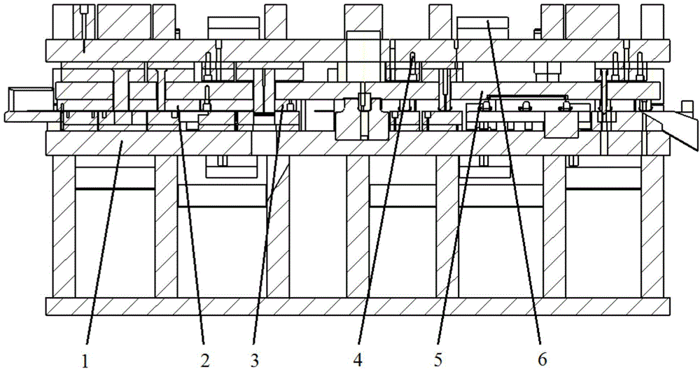
[0020] A mold for continuous production of automobile partition parts, its structure is as figure 1 As shown, it includes an upper module and a lower module that match each other. The relative position and distance between the upper module and the lower module are controlled by guide posts. Specifically, they are set at the four corners of the upper module and the lower module. There are guide posts, so that the upper module and the lower module are connected to each other through the four guide posts.
[0021] The upper die set includes an upper die base 4 and a press plate 5 fixed on the lower surface of the upper die base 4, a punch and an upper die trimming knife block. The press plate 5 is connected to the middle and lower part of the upper die trimming knife block. The head is arranged in the middle of the pressing plate 5. In addition, the upper surface of the upper module is provided with a nitrogen cylinder 6 that drives the upper module to move. The upper die trimming knife block used in this embodiment has an insert block structure, which is convenient for disassembly and replacement.
[0022] The lower module includes a lower mold base 1 and a punch die cutter 2 and a lower mold trimming knife block 3 fixed on the upper surface of the lower mold base 1. Similarly, the lower die trimming block 3 used is also an insert block structure.
[0023] When working, the upper mold base is driven by the press to press the lower mold base, the material to be processed is pressed by the pressing plate, and then the punching punch and the punching die cutter cooperate to perform the punching action, and at the same time, the lower mold trimming block is matched with The mold trimming knife block performs trimming action, and the finished workpiece is formed in one step.

PUM

no PUM

Description & Claims & Application Information

We can also present the details of the Description, Claims and Application information to help users get a comprehensive understanding of the technical details of the patent, such as background art, summary of invention, brief description of drawings, description of embodiments, and other original content. On the other hand, users can also determine the specific scope of protection of the technology through the list of claims; as well as understand the changes in the life cycle of the technology with the presentation of the patent timeline. Login to view more.

Similar technology patents

Punching positioning device

InactiveCN103394731AThe punching position is accurateExtended service life
Owner:STATE GRID CORP OF CHINA +1

Method for preparing abrasion-resistant super-hydrophobic ceramic coating through thermal spraying technology and product

ActiveCN105316619AExtended service lifegood self-cleaning
Owner:NINGBO INST OF MATERIALS TECH & ENG CHINESE ACADEMY OF SCI

Classification and recommendation of technical efficacy words

Why Eureka
Try Eureka