Pressing die for switching box

A technology for pressing molds and switch boxes, applied in the field of compression molds, which can solve the problems of low product processing efficiency and laborious removal, and achieve the effects of convenient removal, convenient unloading, and improved processing efficiency

Inactive Publication Date: 2015-12-23
CHONGQING XIN CHUAN TA IND
View PDF0 Cites 2 Cited by
  • Summary
  • Abstract
  • Description
  • Claims
  • Application Information

AI Technical Summary

Problems solved by technology

[0003] The present invention intends to provide a press mold for a switch box to solve the problems of laborious removal of the substrate of the existing switch box from the lower template and low product processing efficiency

Method used


Image

  • Pressing die for switching box

Examples


Embodiment Construction

[0011] The present invention will be described in further detail below by means of specific embodiments:

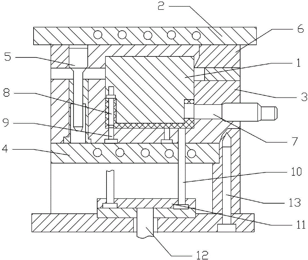
[0012] The reference signs in the drawings of the description include: punch 1, upper heating plate 2, concave mold 3, lower heating plate 4, guide post 5, fixed plate 6, side thread forming core 7, thread forming core 8, core rod 9. Push rod 10, push plate 11, central shaft 12, guide rod 13.

[0013] The embodiment is basically as attached figure 1 Shown: a press mold for a switch box, including an upper heating plate 2 with a punch 1 installed, and a lower heating plate 4 with a die 3 installed, the bottom of the upper heating plate 2 is provided with a guide post 5, and the die 3 is provided with a There is a guide sleeve matching the guide post 5, the bottom of the upper heating plate 2 is connected with a fixed plate 6, a pressure bearing plate is provided between the fixed plate 6 and the die 3, and a side plate is provided between the punch 1 and the die 3. Threa...


PUM


Abstract

The invention discloses a pressing die for a switching box. The pressing die comprises an upper heating plate with a male die and a lower heating plate with a female die. A side threaded plate is arranged between the male die and the female die. A side threaded molding core is arranged on the side threaded plate. The threaded molding core is arranged on the male die. A core rod opposite to the threaded molding core and a push rod penetrating the lower heating plate are arranged on the female die. The push rod is connected with a push plate. A center shaft with an air cylinder is connected to the bottom of the push plate. A supporting plate is connected to the lower heating plate. A guiding rod is arranged inside the supporting plate. A molding cavity of the switching box is defined by the male die, the female die, the threaded molding core, the core rod and the side threaded molding core. The pressing die aims at solving the problems that labor is wasted when a base body of an existing switching box is taken out from a lower die plate and the product machining efficiency is low.

Description

technical field [0001] The invention relates to the technical field of compression molds, in particular to a compression mold for a switch box. Background technique [0002] Switch box is a widely used electrical material, which can be seen everywhere in people's daily life. LED lighting products are lighting appliances made of light sources. Generally, LED lighting products require an external power switch box to provide stable power to them. The existing power switch box generally includes a housing, a power module contained in the housing, a switch and a socket. The switch box is generally made of plastic, and threads are set at the designated positions of the switch box. The existing processing is generally divided into two parts: The first step of processing is completed. First, the matrix is ​​processed by pressing and forming, and then thread processing is performed at the designated position on the matrix. The working process of the pressing mold of the existing swi...

Claims


Application Information

Patent Timeline
Patent Type & Authority Applications(China)
IPC IPC(8): B29C43/42B29C43/52
CPCB29C43/42B29C43/52
Inventor 徐科
Owner CHONGQING XIN CHUAN TA IND
Why Eureka
Try Eureka