
Printing roller coding device

A plate roller and bottom plate technology, applied in the direction of typewriter, printing, etc., can solve the problems of time-consuming, code misalignment, time-consuming and laborious, etc., and achieve the effect of simple implementation, simple operation and convenient use.

Active Publication Date: 2015-12-23
HESHAN SEIKO PLATEMAKING CO LTD
View PDF7 Cites 1 Cited by
  • Summary
  • Abstract
  • Description
  • Claims
  • Application Information

AI Technical Summary

Problems solved by technology

In the traditional coding operation, the workers generally stand up the plate roller, and then put the coding machine at a suitable position on the upper end of the plate roller for coding. This method is time-consuming, labor-intensive, and inefficient, and the coding process is prone to shaking and shifting of the plate roller, resulting in misalignment and overlapping of the codes, requiring re-operation and coding, which consumes a lot of time

Method used


Image

  • Printing roller coding device
  • Printing roller coding device
  • Printing roller coding device

Examples


Embodiment Construction

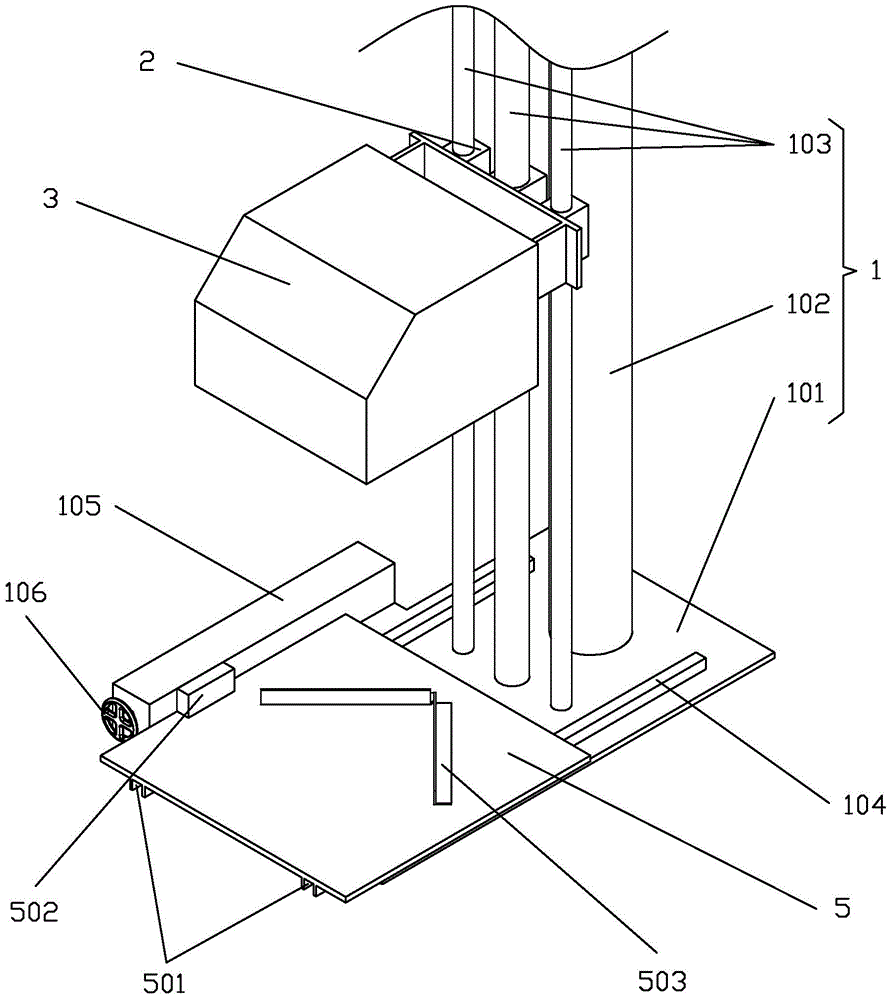
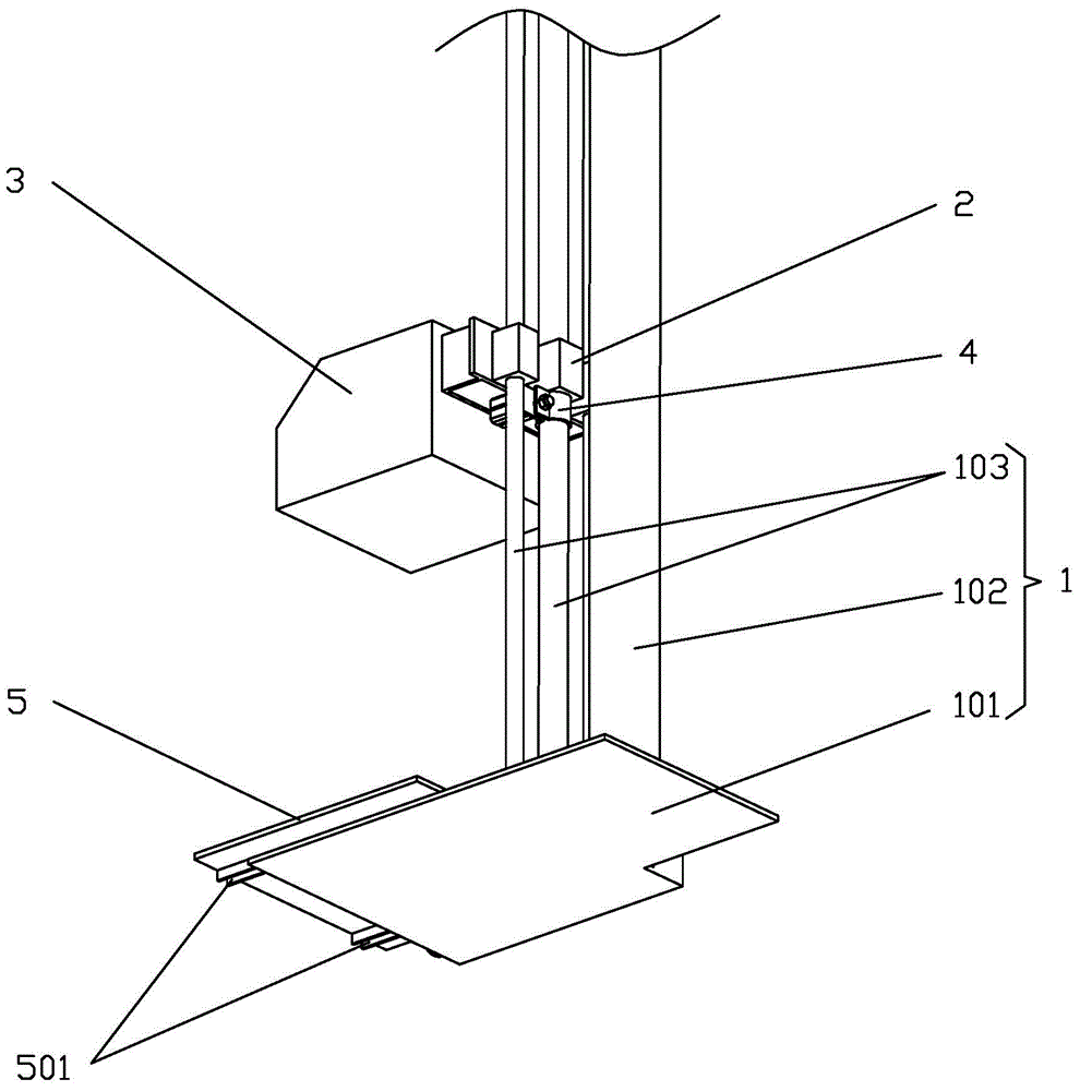
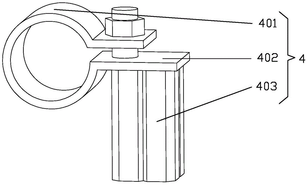
[0016] refer to Figure 1~Figure 4 , a version roller coding device, including a frame 1, the frame 1 includes a bottom plate 101 and a support rod 102 vertically arranged on the bottom plate 101, a guide rod 103, the guide rod 103 is equipped with a The magnetic force cylinder 2, the magnetic force cylinder 2 is connected with a coding machine 3, the locking mechanism 4 located at the lower side of the magnetic force cylinder 2 is installed on the guide rod 103, and the locking mechanism 4 includes a The rod 103 is fitted with an annular plate 401, a gap is reserved between the two ends of the annular plate 401, the two ends of the annular plate 401 extend outward to form a mounting plate 402, one of the mounting plates 402 is connected to a cylinder 403, The piston rod of the air cylinder 403 passes through the two mounting plates 402 and nuts are installed at the ends, and the bottom plate 101 is connected with an adjustment plate 5 for adjusting the position of the plate r...


PUM


Abstract

The invention discloses a printing roller coding device. The printing roller coding device comprises a machine frame. The machine frame comprises a base plate, a supporting rod and guiding rods, wherein the supporting rod and the guiding rods are vertically arranged on the base plate. Magnetic air cylinders which can move up and down are installed on the guiding rods and connected with a coding machine. Locking mechanisms located below the magnetic air cylinders are installed on the guiding rods. Each locking mechanism comprises an annular plate matched with the corresponding guiding rod. A gap is reserved between the two ends of each annular plate. The two ends of each annular plate extend outwards to form installation plates. One installation plate of each annular plate is connected with the corresponding air cylinder. A piston rod of each air cylinder penetrates through the two corresponding installation plates, and a nut is installed at the tail end of the piston rod of each air cylinder. An adjustment plate used for adjusting the position of a printing roller is connected to the base plate.

Description

technical field [0001] The invention relates to a version roller coding device. Background technique [0002] In order to distinguish the version rollers, generally all are coded on one end of the version rollers with a coding machine. In the traditional coding operation, the workers generally stand up the plate roller, and then put the coding machine at a suitable position on the upper end of the plate roller for coding. This method is time-consuming, labor-intensive, and inefficient, and the printing process is prone to shaking and shifting of the plate rollers, resulting in misalignment and overlapping of the codes, requiring re-operation and coding, which consumes a lot of time. Contents of the invention [0003] In order to overcome the deficiencies of the prior art, the present invention provides a coding device for plate rolls, which adjusts the position of the code machine according to the external dimensions of the plate rolls, and is easy to operate and high in ...

Claims


Application Information

Patent Timeline
Patent Type & Authority Applications(China)
IPC IPC(8): B41J3/407
Inventor 王满荣
Owner HESHAN SEIKO PLATEMAKING CO LTD
Learn More