Elastic reverse triggering mechanism

A trigger mechanism and reverse technology, applied in conveyor objects, conveyor control devices, transportation and packaging, etc., can solve the problem of huge data processing capacity, difficult to meet the requirements of the service life of micro switches, and general products without suitable structure and other problems to achieve the effect of reducing damage, increasing service life and improving utilization.

Active Publication Date: 2015-12-23
LUOYANG TST FLAW DETECTION TECH
View PDF6 Cites 1 Cited by
  • Summary
  • Abstract
  • Description
  • Claims
  • Application Information

AI Technical Summary

Problems solved by technology

[0002] At present, for the mechanical touch conveyor belt tear detection equipment, the elastic touch probe has to touch the micro switch continuously when testing the conveyor belt, and the service life of the micro switch cannot meet the requirements, and it requires a huge amount of data processing quantity
In order to solve the above-mentioned problems, the relevant manufacturers have tried their best to find a solution, but for a long time no suitable design has been developed, and the general product has no suitable structure to solve the above-mentioned problems. This is obviously the relevant industry. Urgent problem

Method used


Image

  • Elastic reverse triggering mechanism
  • Elastic reverse triggering mechanism
  • Elastic reverse triggering mechanism

Examples


Embodiment Construction

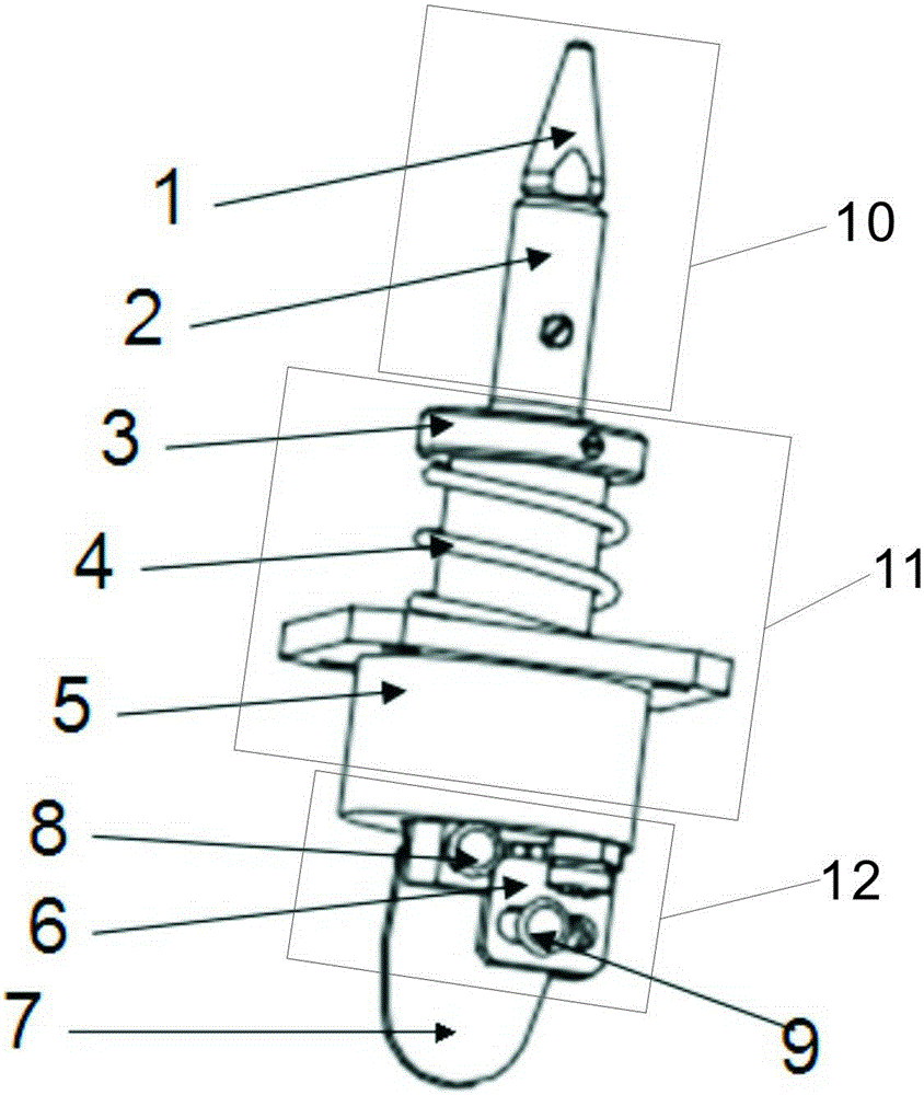
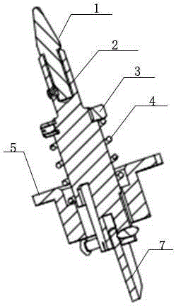
[0022] As shown in the figure, an elastic reverse trigger mechanism is provided with a probe assembly, an elastic telescopic assembly and a reverse assembly. The probe assembly is composed of a probe head 1 and a probe rod 2. The probe head and the external contact end are in the shape of a truncated cone, and the top surface is an arc surface, so that the probe can accurately enter the tearing area of ​​the conveyor belt during detection. One end of the probe head 1 has an external thread, and the probe rod 2 is provided with an internal thread, and the two are connected by threads to form a probe assembly; and the material of the probe head is wear-resistant nylon, which not only protects the conveyor belt in contact with it, but also is not easy to wear. And it can be easily disassembled when worn to a certain extent. In this way, an elastic reverse trigger mechanism can be used reliably and safely for many times, which improves the utilization rate of the product and reduce...


PUM


Abstract

An elastic reverse triggering mechanism is provided with a probe assembly, an elastic extension assembly, a sliding hinge assembly and a reverse wafer. One end of the probe assembly is sleeved with the elastic extension assembly, and the other end of the probe assembly is connected with the sliding hinge assembly. The sliding hinge assembly is connected with the reverse wafer. The state of the surface of a detected object is detected according to the probe assembly. A sensor can be triggered or released according to the state of the surface of the detected object.

Description

technical field [0001] The invention relates to a trigger mechanism, in particular to an elastic reverse trigger mechanism for conveyor belt tear detection. Background technique [0002] At present, for the mechanical touch conveyor belt tear detection equipment, the elastic touch probe has to touch the micro switch continuously when testing the conveyor belt, and the service life of the micro switch cannot meet the requirements, and it requires a huge amount of data processing quantity. In order to solve the above-mentioned problems, the relevant manufacturers have tried their best to find a solution, but no suitable design has been developed for a long time, and the general products do not have a suitable structure to solve the above-mentioned problems. This is obviously the relevant industry. urgent problem to be solved. Therefore, how to create a simple and reliable mechanical mechanism is one of the current important research and development topics, and it has also be...

Claims


Application Information

Patent Timeline
Patent Type & Authority Applications(China)
IPC IPC(8): B65G43/02
Inventor 杨晓序窦伯英杨旭华翔宇
Owner LUOYANG TST FLAW DETECTION TECH
Why Eureka
Try Eureka