Bar push device

A technology of pushing device and bar material, which is applied in the field of robots, can solve the problems of slanting the contact area and smashing the staff, failing to improve work efficiency, and increasing the work intensity of people, so as to achieve the effect of improving work efficiency, simple structure, and avoiding manual pushing.

Active Publication Date: 2015-12-23
青岛萨沃特智能制造技术有限公司
View PDF5 Cites 0 Cited by
  • Summary
  • Abstract
  • Description
  • Claims
  • Application Information

AI Technical Summary

Problems solved by technology

[0002] At present, most of the pushing of bars is carried out manually. Although manual pushing is possible, manual pushing increases the work intensity of people, reduces work efficiency, and increases production costs.
When the material to be pushed is a bar-shaped material, manual pushing can not improve work efficiency, but it is more likely to cause skew and injury to the staff due to the small contact area between the bars.
In addition, some bars such as some radioactive bars are not suitable for manual pushing

Method used


Image

  • Bar push device
  • Bar push device

Examples


Embodiment 1

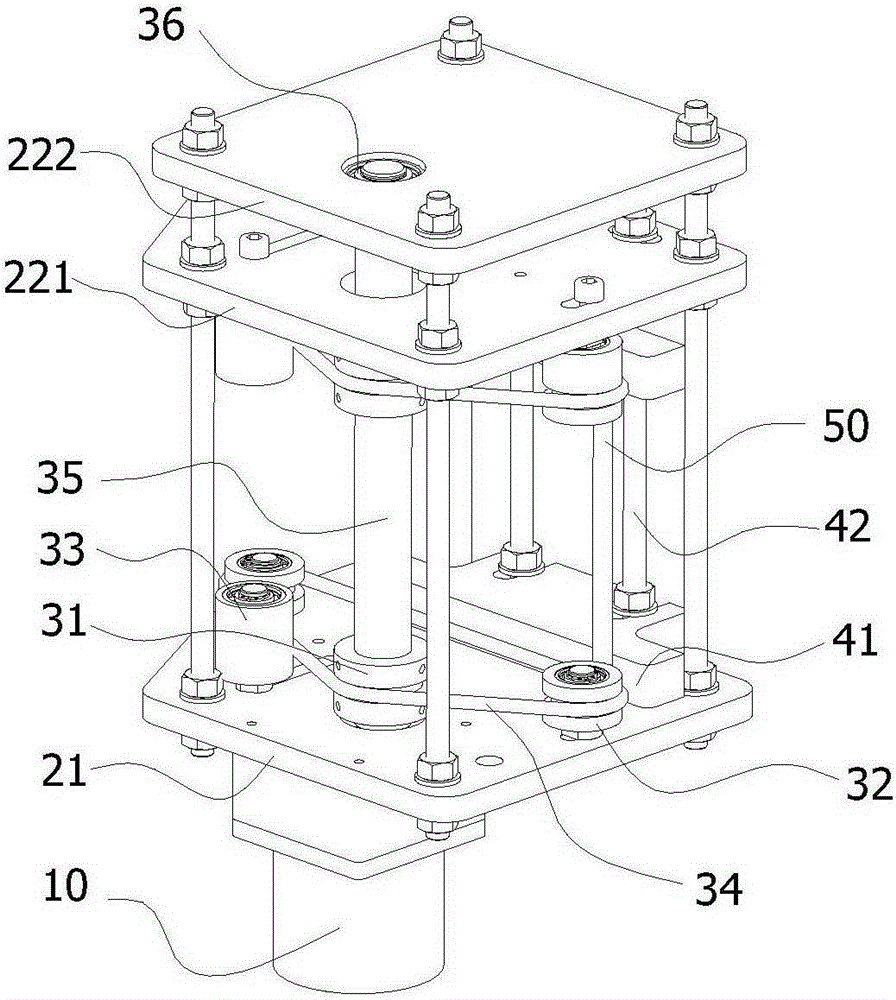
[0025] Such as figure 1 Shown is a perspective view of Embodiment 1 of the bar pushing device of the present invention. figure 1 Among them, the driving part is a servo motor 10, the servo motor 10 is fixed on the base plate 21, and the pushing part includes a driving wheel 31, a driven wheel 32, a tensioning wheel 33 and a conveyor belt 34, and the tensioning wheel 33 is pressed on the conveyor belt 34 for adjusting The degree of tightness of the conveyor belt 34. In this embodiment, the top board includes an inner top board 221 and an outer top board 222 , and the outer top board 222 , the inner top board 221 and the bottom board 21 are fixedly connected by bolts. The driving shaft 35 is fixedly connected to the upper and lower driving wheels 31, the driving shaft 35 passes through the inner top plate 221 and the two ends of the driving shaft 35 are movably connected to the base plate 21 and the outer top plate 222 through the bearing 36. The upper driving wheel and the lo...

Embodiment 2

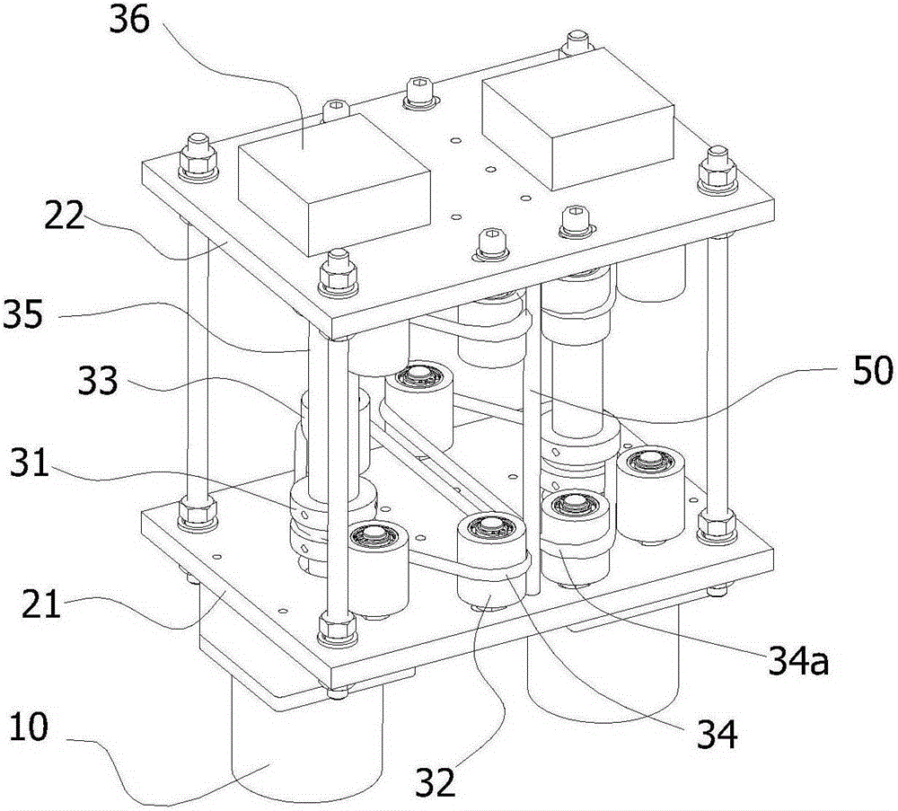
[0029] Such as figure 2 Shown is a perspective view of Embodiment 2 of the bar pushing device of the present invention.

[0030] This embodiment is different from Embodiment 1 in that the top plate in this embodiment is not divided into the upper top plate and the lower top plate, only the top plate 22, one end of the driving shaft 35 is movably connected to the bottom plate 21 and the other end is connected to the top plate 22, and the upper driving wheel and the lower driving wheel 31 are located Between the top plate 22 and the bottom plate 21, the upper driven wheel 32 and the upper tension wheel 33 are movably connected to the top plate 22; the guide part in this embodiment is the mirror image structure of the driving part and the pushing part in the first embodiment. At this time, the bar stock 50 moves between the conveyor belt 34 and the mirror image conveyor belt 34a. When being driven by the conveyor belt 34 and the mirror image conveyor belt 34a, the conveyor belt ...


PUM


Abstract

The invention provides a bar push device which comprises a drive portion, a push portion and a guide portion. The push portion comprises driving wheels, driven wheels, tensioning wheels and conveying belts. The tensioning wheels are arranged between the driving wheels and the driven wheels. The drive portion drives the driving wheels to rotate and drives the conveying belts to move. The conveying belts drive bars to move between the conveying belts and the guide portion. The bar push device is stable and reliable in running, manual pushing is avoided, work efficiency is improved, and production cost is lowered.

Description

technical field [0001] The invention relates to the technical field of robots, in particular to a bar pushing device. Background technique [0002] At present, the pushing of bars is mostly carried out manually. Although manual pushing is possible, manual pushing increases the work intensity of people, reduces work efficiency, and increases production costs. When the material to be pushed is a bar-shaped material, manual pushing can not improve the working efficiency, but on the contrary, it is more likely to skew and injure the staff because of the small contact area between the bars. In addition, some bars such as some radioactive bars are not suitable for manual pushing. Therefore, there is a need for a stable and reliable bar pushing device to replace labor, improve work efficiency, and reduce production costs. Contents of the invention [0003] The object of the present invention is to provide a bar pushing device to solve or partially solve the above problems. [...

Claims


Application Information

Patent Timeline
Patent Type & Authority Applications(China)
IPC IPC(8): B65G47/82
Inventor 李泽伟
Owner 青岛萨沃特智能制造技术有限公司
Why Eureka
Try Eureka