
Beam Construction of Built-in Steel Plate Concrete Composite Shear Wall with End Outsourcing Structure

A steel plate concrete and combined shear wall technology, which is applied to building structures, walls, building components, etc., can solve the problems of poor fire performance, instability and damage of steel plates, and large steel consumption, etc., to achieve good fire performance and improve The effect of ductility level and low cost

Active Publication Date: 2018-12-14
广州市设计院集团有限公司
View PDF9 Cites 0 Cited by
  • Summary
  • Abstract
  • Description
  • Claims
  • Application Information

AI Technical Summary

Problems solved by technology

[0007] One of the purposes of the present invention is to solve the problems of the existing outsourcing steel plate-concrete composite shear wall that the steel plate is prone to local instability and damage, the steel consumption is large, the cost is high and the fire performance is poor. Built-in steel plate concrete composite shear wall with end outsourcing structure

Method used


Image

  • Beam Construction of Built-in Steel Plate Concrete Composite Shear Wall with End Outsourcing Structure
  • Beam Construction of Built-in Steel Plate Concrete Composite Shear Wall with End Outsourcing Structure
  • Beam Construction of Built-in Steel Plate Concrete Composite Shear Wall with End Outsourcing Structure

Examples


specific Embodiment 1

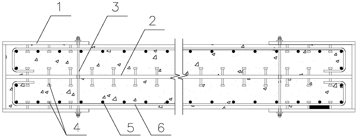
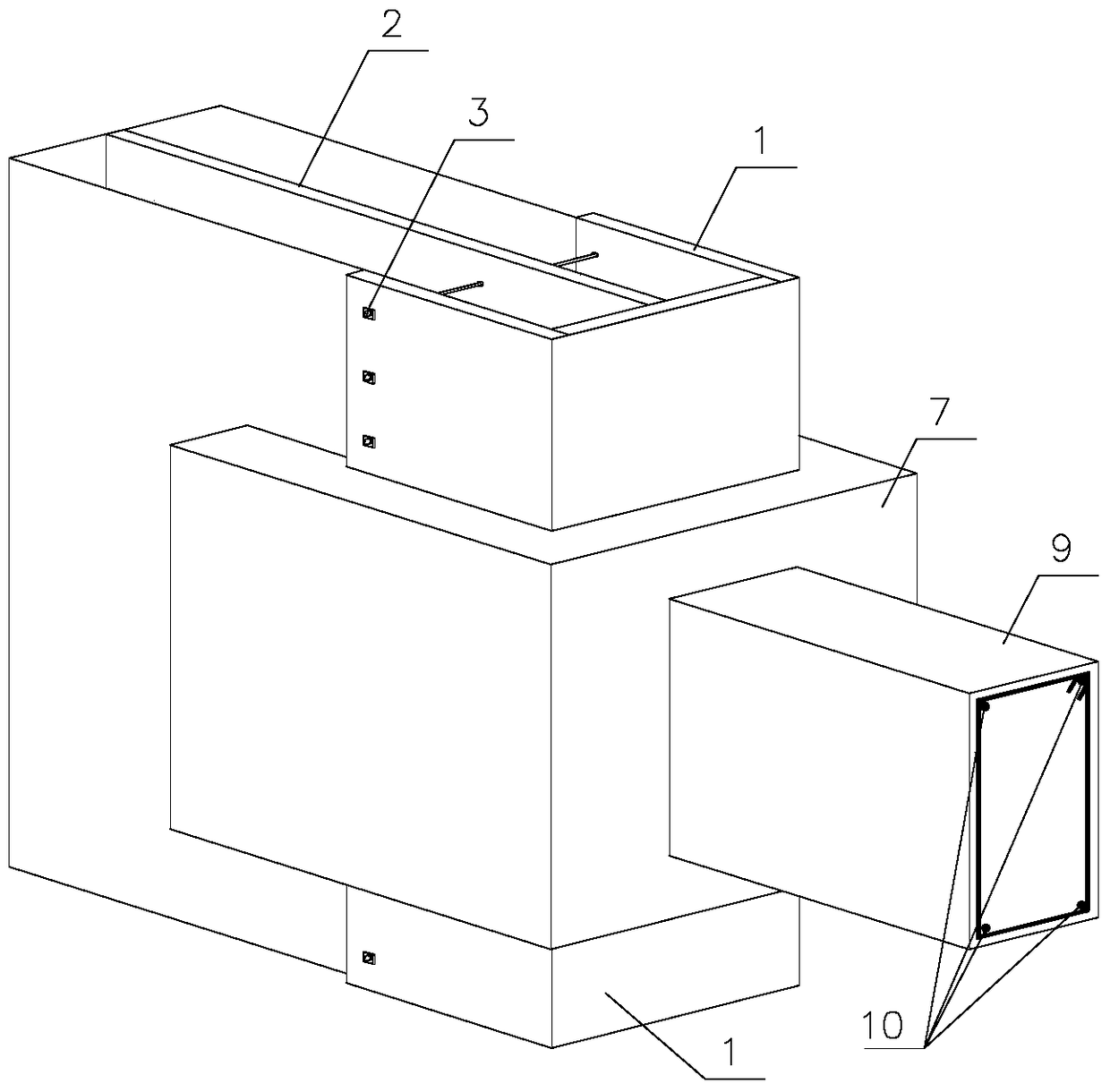
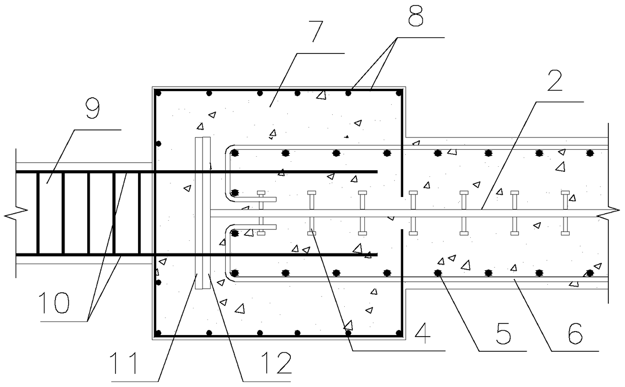
[0028] Reference figure 1 , The built-in steel plate concrete composite shear wall with the end outer envelope structure involved in this embodiment includes a concrete wall and a steel frame structure built into the inner cavity of the concrete wall. A profiled steel outer structure is set at both ends of the concrete wall, so The profiled steel outsourcing structure is composed of profiled steel 1 and a pair of anchor rods 3. The profiled steel 1 is wrapped on the outer surface of the end of the concrete wall and is fixedly connected to the concrete wall and the reinforced frame structure through the anchor rod 3; the reinforced frame structure is composed of A rigid frame structure composed of built-in steel plate 2, vertical distribution ribs 5 and horizontal distribution ribs 6. Both ends of the horizontal distribution ribs 6 are fixedly connected to the two ends of the built-in steel plate 2 through nails 4, and the vertical distribution ribs 5 are connected to the horizont...


PUM


Abstract

The invention relates to an internal steel plate-concrete composite shear wall with end part externally-wrapping structures, and a cross beam structure. The internal steel plate-concrete composite shear wall with the end part externally-wrapping structures comprises a concrete wall body and a steel bar frame structure internally arranged in an inner cavity of the concrete wall body, and is characterized in section steel externally-wrapping structures at the two ends of the concrete wall body, each section steel externally-wrapping structure is composed of section steel and cross anchor rods, and the section steel wraps the outer end surfaces of the end parts of the concrete wall body and is fixedly connected with the concrete wall body and the steel bar frame structure through the cross anchor rods; the steel bar frame structure is a rigid frame structure composed of the internal steel plate, vertically distributed bars and horizontally distributed bars, the two ends of each horizontally distributed bar are fixedly connected with the two ends of the internal steel plate through studs respectively, and the vertically distributed bars and the horizontally distributed bars are in binding connection to form the rigid frame structure; and the two ends of the internal steel plate contact with a web plate of the section steel, and the two flanges of the section steel are fixed on the concrete wall body and the steel bar frame structure through the cross anchor rods to form each end part externally-wrapping structure. The internal steel plate-concrete composite shear wall with the end part externally-wrapping structures, which is disclosed by the invention, has the beneficial effects of being good in fireproof performance, good in steel plate buckling-restrained performance, low in cost, and high in ductility level.

Description

Technical field [0001] The invention relates to a hybrid shear wall, in particular to a built-in steel plate concrete composite shear wall and cross beam structure with an end outer envelope structure. It belongs to the technical field of building structure. Background technique [0002] With the development of construction technology and social needs, high-rise and super-high-rise buildings are emerging in endlessly. As the height of buildings increases, as the main lateral force-resisting component in the building-shear wall, if the traditional form of reinforced concrete is adopted, the thickness will not only be too thick Affect the use, and the economy is poor and the safety is low. Therefore, the steel-concrete composite shear wall came into being. [0003] In the prior art, steel-concrete composite shear walls mainly include: steel-concrete composite shear walls, steel-concrete composite shear walls, steel pipe-concrete composite shear walls, steel support-concrete composi...

Claims


Application Information

Patent Timeline
Patent Type & Authority Patents(China)
IPC IPC(8): E04B1/38E04B1/58E04B1/14E04B1/24E04B1/20E04B1/21E04B2/84
Inventor 韩建强王一功徐刚
Owner 广州市设计院集团有限公司
Learn More