
Automatic Wall Builder

A wall-laying machine, automatic technology, applied in the direction of construction, building structure, building materials processing, etc., can solve the problems of labor intensity of the operator, high potential safety hazards, low efficiency, etc., to achieve reduced labor intensity, convenient operation, Hazardous effects of working at heights

Active Publication Date: 2017-05-10
山东岱圣建设有限公司
View PDF4 Cites 3 Cited by
  • Summary
  • Abstract
  • Description
  • Claims
  • Application Information

AI Technical Summary

Problems solved by technology

However, most of the walls of masonry structures are piled up by manual operation, and high-risk and cumbersome operations such as manually pulling wires to measure parallelism and climbing scaffolding are not only inefficient, but also have high labor intensity and safety hazards for the operators, which cannot meet the current requirements in my country. Requirements for efficient and automated operations

Method used


Image

  • Automatic Wall Builder
  • Automatic Wall Builder
  • Automatic Wall Builder

Examples


Embodiment Construction

[0033] The preferred embodiments of the present invention will be described in detail below in conjunction with the accompanying drawings.

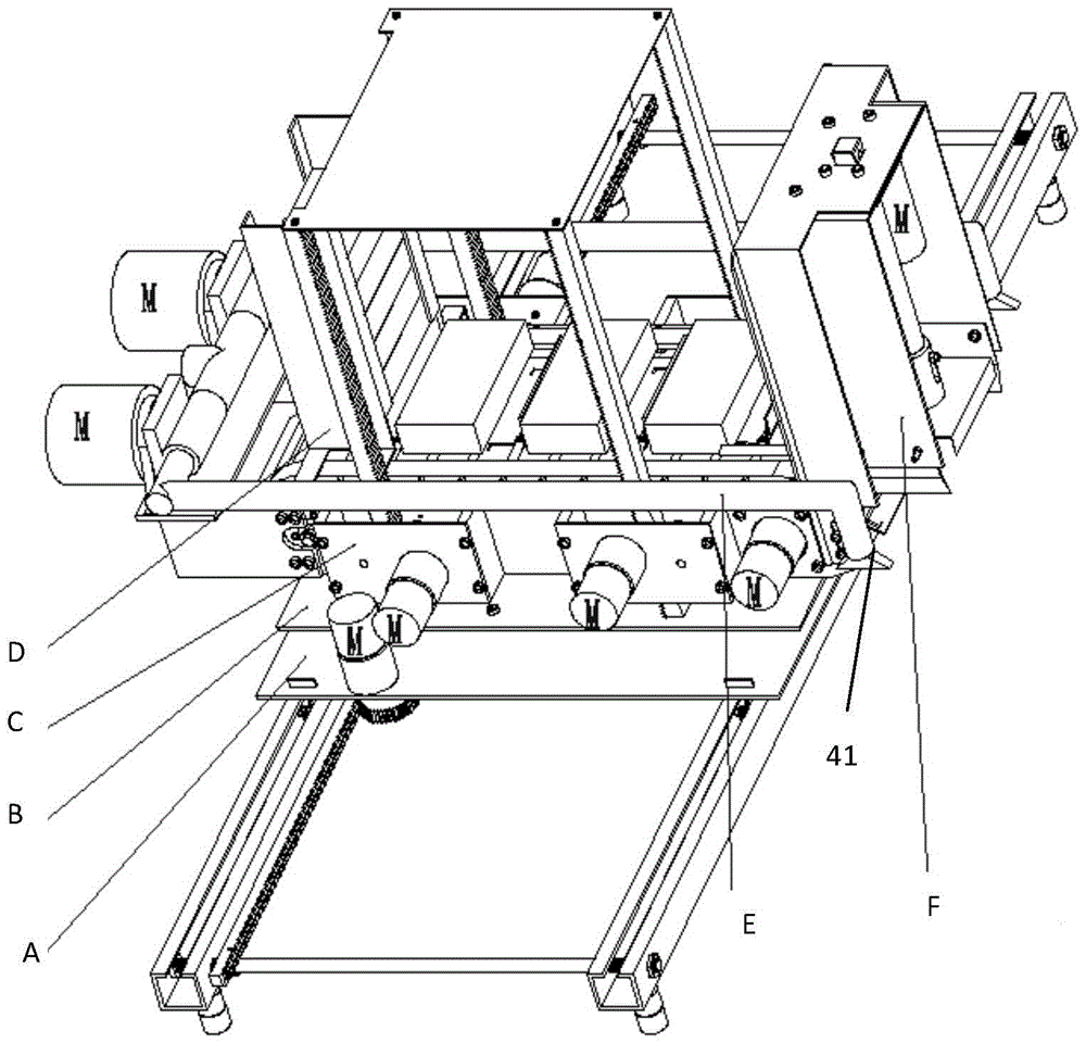
[0034] Refer to attached Picture 1-1 0. The automatic wall-laying machine in this embodiment includes a longitudinal movement mechanism A, a transverse movement mechanism B, a vertical lifting mechanism C, a brick transmission mechanism D, a mortar spraying mechanism E, and a brick falling mechanism F. Each mechanism and the cooperation structure between the mechanisms will be described in detail below.

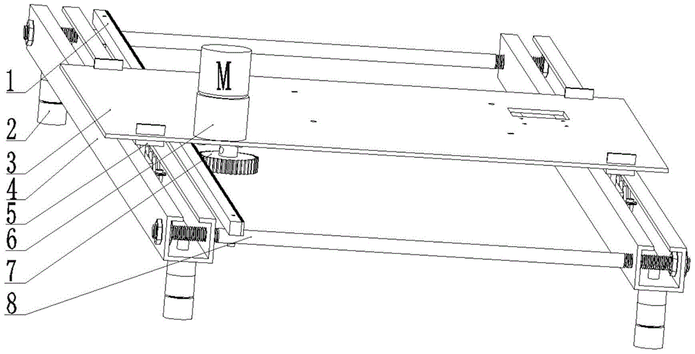
[0035] Longitudinal motion mechanism A comprises two parallel guide rails 4, adjustment screw rod 8, adjustment support foot 2, six-wheel guide wheel 5, base plate 3, motor 6, gear 7, rack 1, two guide rails 4 are arranged in parallel, two guide rails 4 two The ends are respectively fixedly connected by a screw rod 8 which can adjust the distance of the guide rail, and the screw rod 8 is perpendicular to the guide rail 4 . Two height-...


PUM


Abstract

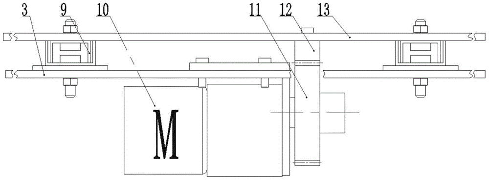
The invention discloses an automatic wall-building machine, characterized by comprising a longitudinal movement mechanism (A), a transverse movement mechanism (B), a vertical lifting mechanism (C), a brick conveying mechanism (D), a mortar spraying mechanism (E), and a brick discharging mechanism (F). The longitudinal movement mechanism (A) comprises two guide rails (4) which are parallel. A first bottom plate (3) is slidably fitted on the two guide rails (4). The transverse movement mechanism (B) comprises a second bottom plate (13) which is mounted on the first bottom plate (3) through a moving slide rail (9). A horizontal movement direction of the moving slide rail (9) is parallel to that of the first bottom plate (3). The vertical lifting mechanism (C) is arranged on the second bottom plate (13). The brick conveying mechanism (D), the mortar spraying mechanism (E) and the brick discharging mechanism (F) are arranged on the vertical lifting mechanism (C). The brick conveying mechanism (D) is used for conveying bricks. A conveying exit of the brick conveying mechanism (D) is located opposing a discharge exit of the brick discharging mechanism (F). A mortar spout of the mortar spraying mechanism (E) exactly faces the discharge exit of the brick discharging mechanism (F).

Description

technical field [0001] The invention belongs to the technical field of construction equipment manufacturing, in particular to a device suitable for building inner walls and outer walls after wall piers are built. Background technique [0002] Masonry structure has always been a structural form popularized in a large area in my country, and is suitable for various buildings. In recent years, my country's construction industry has been highly developed. However, the walls of masonry structures are mostly piled up by manual operation, which requires high-risk and cumbersome operations such as pulling wires to measure parallelism and climbing scaffolding. Requirements for efficient automation operations. In order to improve efficiency and reduce labor intensity, there is an urgent need for a wall-building equipment that integrates automatic brick taking, mortar spraying, brick laying and compaction. Contents of the invention [0003] In order to solve the above-mentioned pro...

Claims


Application Information

Patent Timeline
Patent Type & Authority Patents(China)
IPC IPC(8): E04G21/22
Inventor 黄金永林佳辉黄磊黄明钧
Owner 山东岱圣建设有限公司
Learn More