Main pump shaft seal water leakage monitoring device

A pump shaft and monitoring sensor technology, applied in pump control, liquid variable capacity machinery, machine/engine, etc., can solve problems such as failure to detect the main pump shaft seal and water leakage in time, and reduce system misoperation and misjudgment. The effect of risk, simple monitoring loop and reasonable control logic

Active Publication Date: 2015-12-23
CHANGZHOU BORI ELECTRIC POWER AUTOMATION EQUIP
View PDF6 Cites 3 Cited by
  • Summary
  • Abstract
  • Description
  • Claims
  • Application Information

AI Technical Summary

Problems solved by technology

However, due to the blockage of the outlet pipeline or the failure of the water level sensor, the system will fail to detect the leakage of the shaft seal of the main pump in time and cause serious consequences.

Method used


Image

  • Main pump shaft seal water leakage monitoring device

Examples


Embodiment Construction

[0020] In order to make the content of the present invention more clearly understood, the present invention will be further described in detail below based on specific embodiments and in conjunction with the accompanying drawings.

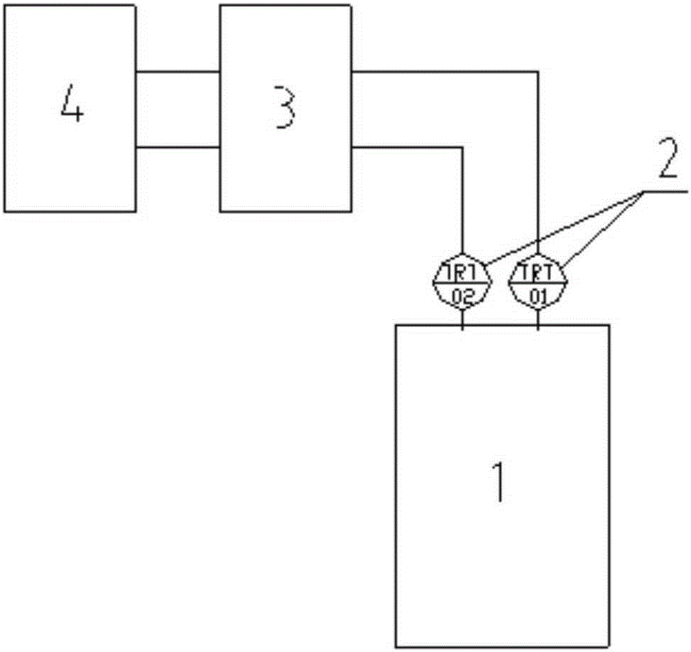
[0021] Such as figure 1 As shown, a device for monitoring the leakage of the shaft seal of the main pump includes:

[0022] A valve cooling control system, the valve cooling control system is provided with a monitoring loop 3;

[0023] A monitoring sensor 2, the monitoring sensor 2 has a temperature sensor and / or a humidity sensor, and the signal output end of the monitoring sensor 2 is connected to the signal input end of the monitoring circuit 3, and the monitoring sensor 2 is used to collect the temperature at the shaft seal of the main pump signal and / or humidity signal, and transmit it to the monitoring circuit 3; the monitoring sensor 2 adopts an integrated temperature and humidity sensor, and the redundant configuration of the temperature a...


PUM


Abstract

The invention discloses a main pump shaft seal water leakage monitoring device. The device comprises a valve cooling control system, a monitoring sensor and an alarm loop. A monitoring loop is arranged in the valve cooling control system, the monitoring sensor is provided with a temperature sensor and/or a humidity sensor, and the signal output end of the monitoring sensor is connected with the signal input end of the monitoring loop; the monitoring sensor is used for collecting temperature signals and/or humidity signals at a main shaft seal and transmits the signals to the monitoring loop; and the signal input end of the alarm loop is connected with the signal output end of the monitoring loop, and the alarm loop is used for giving out an alarm motion according to the received alarm signals transmitted by the monitoring loop. According to the device, the main pump shaft seal water leakage condition can be rapidly, efficiently and accurately monitored, and stability and reliability of a direct-current valve cooling system and even a converter valve are ensured.

Description

technical field [0001] The invention relates to a device for monitoring water leakage of a shaft seal of a main pump. Background technique [0002] At present, in my country's power system, high-voltage direct current transmission technology is widely used. As one of the core equipment of high-voltage direct current transmission, the high-voltage direct current transmission converter valve is very important for its safe, stable and continuous operation. The DC transmission converter valve water cooling system using pure water cooling technology solves the problem of reliable heat dissipation of the converter valve and ensures that the operating junction temperature of the converter valve device does not exceed the maximum allowable junction temperature. In the high-voltage direct current transmission projects that have been put into operation, cases of direct current blocking caused by faults in the direct current valve cooling system are not uncommon. As the core component...

Claims


Application Information

Patent Timeline
Patent Type & Authority Applications(China)
IPC IPC(8): F04B49/10
Inventor 赵盛国张辉亮陈武张潆月恽强龙
Owner CHANGZHOU BORI ELECTRIC POWER AUTOMATION EQUIP
Why Eureka
Try Eureka