Elastic clamping type connecting piece

A technology of elastic clamping and clamping parts, applied in the direction of connecting components, rods, mechanical equipment, etc., can solve the problems of insufficient fast and convenient connection, falling of the snap ring, and inability to achieve docking, etc., to ensure tightness and fastness , Easy assembly and convenient connection

Active Publication Date: 2015-12-23
浙江兆弟技术有限公司
View PDF10 Cites 10 Cited by
  • Summary
  • Abstract
  • Description
  • Claims
  • Application Information

AI Technical Summary

Problems solved by technology

However, this solution needs to assemble the intermediate nut, elastic member, and snap ring at one time during assembly, and the assembly of the snap ring needs to be careful, otherwise it will easily cause the snap ring to fall and fail to achieve docking, so the connection is not fast and convenient.

Method used


Image

  • Elastic clamping type connecting piece
  • Elastic clamping type connecting piece
  • Elastic clamping type connecting piece

Examples


Embodiment 1

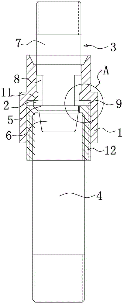
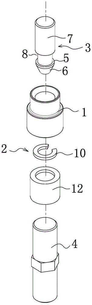
[0024] Such as figure 1 As shown, an elastic snap-in connector includes a connecting nut 1 through which the upper and lower ends penetrate. The connecting nut 1 is internally movably connected with an elastic snap-in member 2, and one end of the connecting nut 1 is inserted into the There is a plug connector 3, and the other end is screwed with a screw connector 4, and the plug connector 3 has a card table 5. When the plug connector 3 is inserted into the clip connector 2, the clip Part 2 can move away from the axis of the connecting nut 1, and when the clamping platform 5 on the connector 3 passes through the clamping part 2, the clamping part 2 can move in a direction close to the axis of the connecting nut 1 so that the clamping The connecting piece 2 is stuck on the card platform 5 .

[0025] The end of the plug connector 3 away from the card table 5 has an external thread, and the end of the intermediate nut 12 close to the plug connector 3 has a chamfer. The screw joi...

Embodiment 2

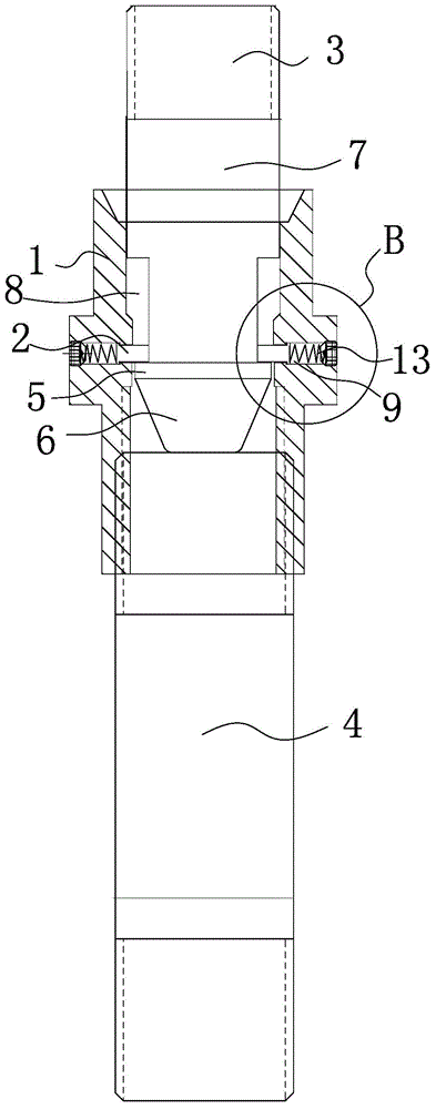
[0031] The structure and working principle of this embodiment are basically the same as that of Embodiment 1, the difference is that, as figure 2 As shown, the clip 2 includes a spring 13 and a latch 14. The spring 13 is located in the clip accommodating cavity 9. In this embodiment, there is at least one clip accommodating cavity 9, and there may be A plurality of them are symmetrically distributed along the axis of the connecting nut 1 , and as for the shape of the clip accommodating cavity 9 , those skilled in the art should understand that it only needs to be matched with the spring member 13 , so it is not specifically limited. One end of the pin 14 abuts against the spring element 13 , and the other end extends out of the clamping element accommodating cavity 9 under the elastic force of the spring element 13 , and the pin 14 can reciprocate along its axis under the elastic force of the elastic element 13 .

[0032] The screw joint 4 is cylindrical, and the end close to...


PUM


Abstract

The invention belongs to the technical field of buildings and relates to an elastic clamping type connecting piece. The elastic clamping type connecting piece comprises a connecting nut, wherein the upper end and the lower end of the connecting nut are through. An elastic clamping part is movably connected into the connecting nut. A connector clip is inserted in one end of the connecting nut. The other end of the connecting nut is in screw joint with a screw joint part. The connector clip is provided with a clamping platform. When the connector clip is inserted into the clamping part, the clamping part can move in the direction far from the axis line of the connecting nut; when the clamping platform on the connector clip passes through the clamping part, the clamping part can move in the direction close to the axis line of the connecting nut to make the clamping part clamp the clamping platform. The elastic clamping type connecting piece can be used for connection of two objects and is convenient to assemble, convenient and fast to connect and firm and reliable in connection.

Description

technical field [0001] The invention belongs to the technical field of construction, and relates to an elastic snap-fit ​​connector, which is suitable for the connection between two objects. Background technique [0002] The applicant’s previous application for a patented strong tension connection connector [Application No.: 201510314380.0] includes a first tension nut and a second tension nut respectively fixed at both ends of the prefabricated part. The first tension nut can be The insertion rod is disassembled and connected, and the middle nut is detachably connected to the second tension nut. The second tension nut is provided with an elastic member, and a snap ring is arranged between the intermediate nut and the elastic member. When the insertion rod is inserted When entering the middle nut, the snap ring can hold the insertion rod, the middle nut includes a nut body, the outer wall of the nut body has external threads, and the inside of the nut body is provided with a...

Claims


Application Information

Patent Timeline
Patent Type & Authority Applications(China)
IPC IPC(8): F16B7/06
Inventor 周兆弟
Owner 浙江兆弟技术有限公司
Why Eureka
Try Eureka