Central heating system and method with heat accumulation peak regulation function

A centralized heating and cooling system technology, applied to heating systems and centralized heating, can solve the problems of high heat transmission and distribution costs, increased operating costs, mutual interference, etc., achieve low heat transmission and distribution costs, realize room-by-room temperature control, Eliminates the effect of wild swings

Inactive Publication Date: 2015-12-23
朱杰
View PDF7 Cites 12 Cited by
  • Summary
  • Abstract
  • Description
  • Claims
  • Application Information

AI Technical Summary

Problems solved by technology

[0023] 1. In the existing system, a linked cycle is formed from the heating network to the end, which interferes with each other and makes adjustment difficult
[0024] 2. After adopting heat metering and charging, "behavioral energy saving" leads to increased fluctuation of terminal load, lagging response ability of heating network, and high cost of heat transmission and distribution;
[0025] 3. If the on-off

Method used


Image

  • Central heating system and method with heat accumulation peak regulation function
  • Central heating system and method with heat accumulation peak regulation function
  • Central heating system and method with heat accumulation peak regulation function

Examples


Embodiment 1

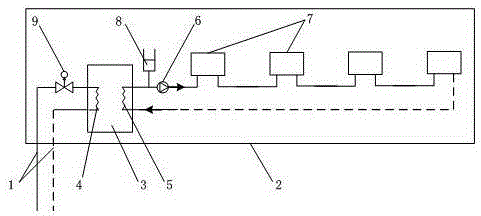
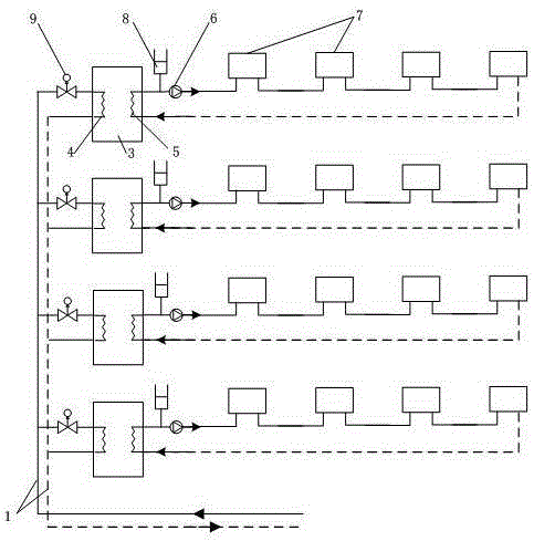
[0066] For the household-level loop system, each user is an independent branch line, and the "on-off time area method" system is usually used at present. Such as figure 2 As shown, this type of system can be upgraded and transformed, and the heat storage peak shaving terminal system of the present invention is installed at the heat inlet of each user.

[0067] At this time, each end user can control independently, and the interface of the inner heat exchanger 5 is open to the end user, and each end user can freely choose the internal heat dissipation system 7, such as radiator, radiant heating or fan coil, all can be very good match with the heat storage / heat exchange module 3.

[0068] After the transformation, the distance between the heating network 1 and the pipelines connected to each user is very short, and packaging means can be adopted to prevent users from damaging this part, so as to prevent the behavior of stealing water.

Embodiment 2

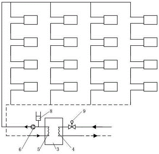
[0070] For the single-pipe vertical series system, most of them are existing residential buildings or public buildings. This type of building should adopt the overall heat storage peak-shaving system of the building, that is, the entire building as an end system (such as image 3 shown). Install the heat storage peak-shaving terminal system of the present invention at the thermal entrance of the building to conduct unified control and management of the entire building.

[0071] At this time, different types of terminal systems can be freely selected based on the building as a unit, such as radiators, radiant heating or fan coil units, all of which can be well matched with the heat storage / exchange module 3 . The heat storage capacity of the heat storage / exchange module 3 should also be equipped according to the overall heat load of the building.

[0072] Moreover, it is still possible to preset the heating demand for each terminal, and after collecting the settings of each t...


PUM


Abstract

The invention provides a central heating system with a heat accumulation peak regulation function. The central heating system comprises a heat supply network (1) and a terminal system (2), and is characterized in that the terminal system (2) comprises a heat accumulation/exchange module (3), a heat supply network side heat exchanger (4), an inner side heat exchanger (5), an internal circulating pump (6) and an internal cooling system (7). By the adoption of the central heating system and method, enhancement of the self-adaptation performance of a terminal and simplification of the control process are achieved by means of distributed heat accumulation, and therefore high-efficiency and low-cost operation is achieved.

Description

technical field [0001] The invention relates to a centralized heat supply system and method that utilizes distributed heat storage means, enhances the self-adaptive performance of the terminal, simplifies the control process, and realizes high-efficiency and low-cost operation. The invention belongs to the technical field of central heating system design and control. Background technique [0002] With the continuous development of China's heating metering reform, the system structure of the heating system has undergone great changes. In order to adapt to this structural change, high requirements are put forward for the system's regulation ability and automation degree. [0003] One of the main goals of heat metering reform is to save energy. Under such a major premise, for the central heating system, it is necessary to achieve two points: "heating on demand" for heat sources and "heating on demand" for heat users. [0004] On-demand heating, simply put, means that the heat...

Claims


Application Information

Patent Timeline
IPC IPC(8): F24D11/00F24D19/10
Inventor 朱杰
Owner 朱杰
Why Eureka
Try Eureka