Sensor calibration device
A calibration device and sensor technology, which is applied in the direction of measuring devices, instruments, scientific instruments, etc., can solve the problems of T90 response time not reaching the standard, calibration and detection impact, etc., and achieve the effect of simple structure and convenient calibration operation
- Summary
- Abstract
- Description
- Claims
- Application Information
AI Technical Summary
Problems solved by technology
Method used
Image

Examples
specific Embodiment approach 1
[0015] A sensor calibration device, comprising a cylindrical bottom surface (2-2), a boss (2-1), and a cylindrical thin-walled ring (1-2), characterized in that: the cylindrical thin-walled ring is connected to the top of the cylindrical bottom surface (2-2) (1-2) and the boss (2-1), the boss (2-1) is located inside the cylindrical thin-walled ring (1-2), and the bottom surface of the cylinder (2-2) is provided with a bottom exhaust hole (3-1) and air intake holes (3-2), the inside of the boss (2-1) is provided with exhaust holes and air intake holes (3-2) corresponding to the bottom surface of the cylinder (2-2) .
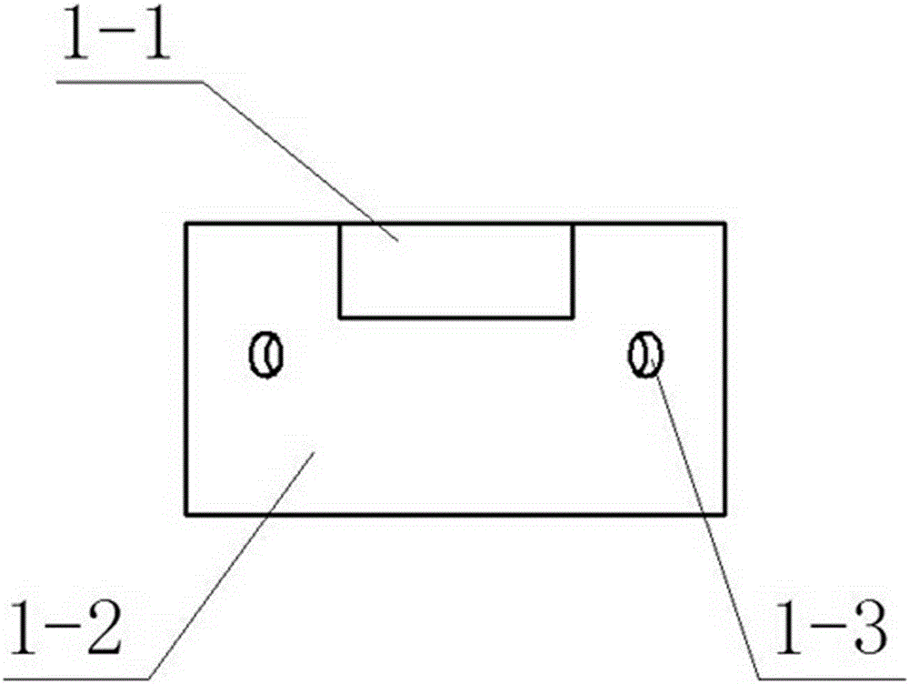
[0016] The cylindrical thin-walled ring (1-2) is provided with a positioning groove (1-1), and a plurality of side exhaust holes (1-3) are arranged around the cylindrical thin-walled ring (1-2).
[0017] There are two bottom exhaust holes (3-1), and there are also two corresponding exhaust holes on the boss (2-1).
specific Embodiment approach 2
[0019] Such as figure 1 As shown, the front view structure includes a positioning groove (1-1), a cylindrical thin-walled ring (1-2), and a side exhaust hole (1-3). The positioning groove (1-1) is located at the upper end of the cylindrical thin-walled ring (1-2), and can be assembled with the sensor cover to rotate 360 degrees so that the air inlet is aligned with the position of the sensor with strong adsorption force, and the side exhaust hole (1 -3) Exhaust is evenly distributed around the cylindrical thin-walled ring.
specific Embodiment approach 3
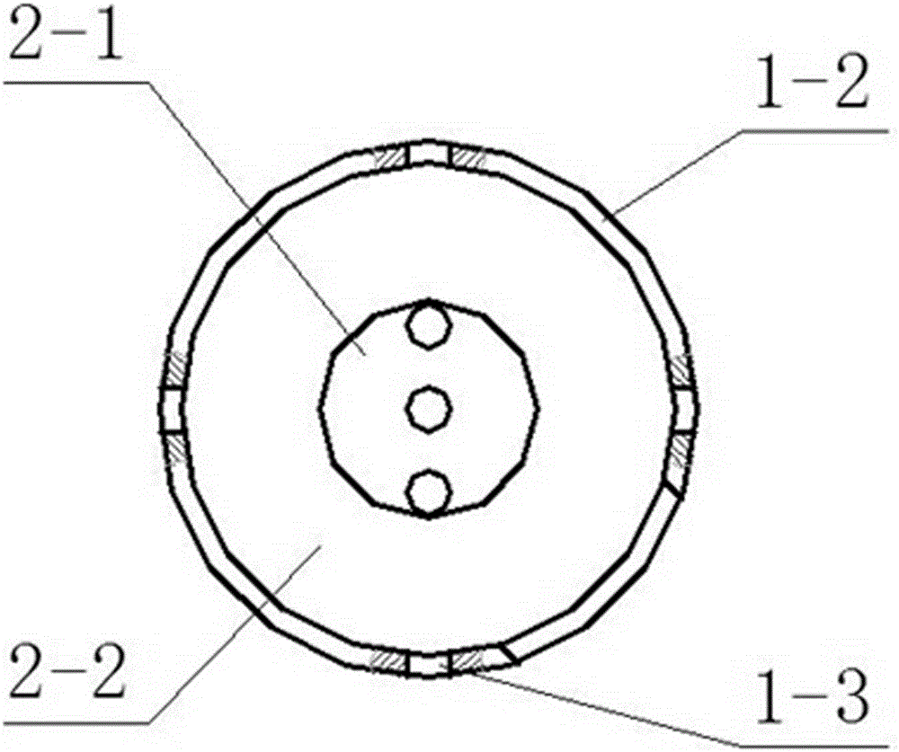
[0021] Such as figure 2 As shown, the top view structure includes a boss (2-1), a cylindrical bottom surface (2-2), a side exhaust hole (1-3), and a cylindrical thin-walled ring (1-2). The boss (2-1) and the cylindrical thin-walled ring (1-2) are located on the upper part of the bottom surface (2-2).
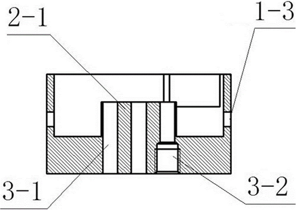
[0022] like image 3 As shown, the cross-sectional structure includes a bottom exhaust hole (3-1), an air intake hole (3-2), a side exhaust hole (1-3) and a boss (2-1). The bottom exhaust hole (3-1) and air inlet hole (3-2) pass through the boss (2-1) and are connected to the sensor ground for gas detection.
PUM
 Abstract
Description
Claims
Application Information
 - R&D
- Intellectual Property
- Life Sciences
- Materials
- Tech Scout
- Unparalleled Data Quality
- Higher Quality Content
- 60% Fewer Hallucinations
Browse by: Latest US Patents, China's latest patents, Technical Efficacy Thesaurus, Application Domain, Technology Topic, Popular Technical Reports.
© 2025 PatSnap. All rights reserved.Legal|Privacy policy|Modern Slavery Act Transparency Statement|Sitemap|About US| Contact US: help@patsnap.com