Protective device for avoiding optical lens surface scratch

A technology for optical mirrors and protection devices, applied in optics, optical components, installation, etc., can solve problems such as scratches, achieve good positioning, save space, and have a simple structure

Inactive Publication Date: 2015-12-23
XI'AN INST OF OPTICS & FINE MECHANICS - CHINESE ACAD OF SCI
View PDF3 Cites 3 Cited by
  • Summary
  • Abstract
  • Description
  • Claims
  • Application Information

AI Technical Summary

Problems solved by technology

Especially for a single lens with non-concave surfaces on both sides or a lens group in which the mirror surface is higher than the fr

Method used


Image

  • Protective device for avoiding optical lens surface scratch
  • Protective device for avoiding optical lens surface scratch
  • Protective device for avoiding optical lens surface scratch

Examples


Example Embodiment

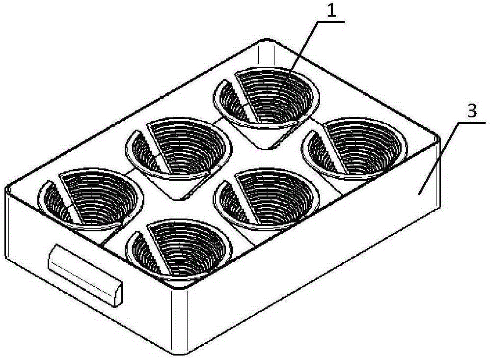
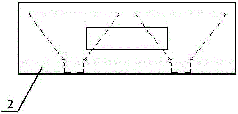
[0023] like Figures 1 to 5 As shown, the protective device for preventing scratches on the optical mirror surface of the present invention mainly includes a box body, a mirror holder and a mirror holder seat. The mirror holder is assembled on the mirror holder seat, and the mirror holder holder is placed in the box body, and the box body is provided with a dustproof cover.

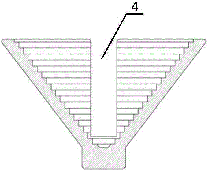
[0024] The inner wall of the mirror holder is designed with an annular stepped surface distributed in a step shape, and the inner diameter of the annular stepped surface is larger than the inner diameter of the non-working surface of the optical lens to be placed on it. like Image 6 As shown, the non-working surface of the optical lens mentioned here is the inward annular zone (usually unilateral 1mm) of the optical lens, and the inner side of the annular zone is the light-passing aperture. If it is an optical lens equipped with a frame, the frame will also have a wall thickness equivalent to the size ...


PUM


Abstract

The present invention provides a protective device for avoiding optical lens surface scratch, and the protective device can avoid scratch caused by the lens storage box carrying. The protective device mainly includes a box body, lens holders and a lens holder support. The lens holder support is putted in the box body, and the box body is provided with a dust cover. The inner wall of the lens holder is provided with multi-step annular stepped faces, wherein, the multi-step annular stepped faces are in a cone-shaped distribution mode on the whole, and the inner diameter of each step of the annular stepped faces is larger than the inner diameter of a non-work face of the optical lens to be putted so as to ensure the non-contact placement of the optical lens. The inner wall of the lens holder is symmetrically provided with a trough passing through the multi-step annular stepped faces so as to take out and put lens conveniently. The protective device has the simple structure and saves the space, a plurality of lens with various sizes can be putted in the same lens holder through the multi-step annular steps, and the optical lens can be exactly putted on the annular stepped face which is suitable for the outer diameter of the optical lens.

Description

technical field [0001] The invention relates to a protection device for preventing optical mirror surface from being scratched during the assembly and adjustment of an optical system. Background technique [0002] With the wide application of space vehicles, photoelectric detection and military guidance, scientific experiments and other fields, the demand for high-precision optical lenses for various purposes is also increasing. Due to the high precision requirements of this type of optical system, the design requirements of optical mechanical parts are high, the manufacturing cycle is long, and the cost is expensive. This inevitably requires striving for zero error rate and zero scratches on the optical mirror during the assembly and adjustment process. In the traditional assembly and adjustment process: a single lens that is not in the frame or a single lens group that is in the frame is placed flat in a flat-bottomed storage box. Since the flat-bottomed storage box does ...

Claims


Application Information

Patent Timeline
IPC IPC(8): G02B7/02
CPCG02B7/02
Inventor 李小燕王鹏韩娟耿波段占军
Owner XI'AN INST OF OPTICS & FINE MECHANICS - CHINESE ACAD OF SCI
Why Eureka
Try Eureka