Rotary power supply device

A technology of rotating power supply and rotating shaft, which is applied in the direction of flexible/rotatable wire connectors, circuits, electrical components, etc. It can solve the problem that the rotating part cannot rotate 360 ​​degrees infinitely, and achieve the effect of convenient control, reliable power supply and simple structure

Active Publication Date: 2015-12-23
上海青芒智能科技有限公司
View PDF5 Cites 7 Cited by
  • Summary
  • Abstract
  • Description
  • Claims
  • Application Information

AI Technical Summary

Problems solved by technology

[0004] The purpose of the present invention is to provide a rotating power supply device, which effectively solves the problem that the rotating part cannot rotate 360 ​​degrees infinitely

Method used


Image

  • Rotary power supply device
  • Rotary power supply device

Examples


Embodiment Construction

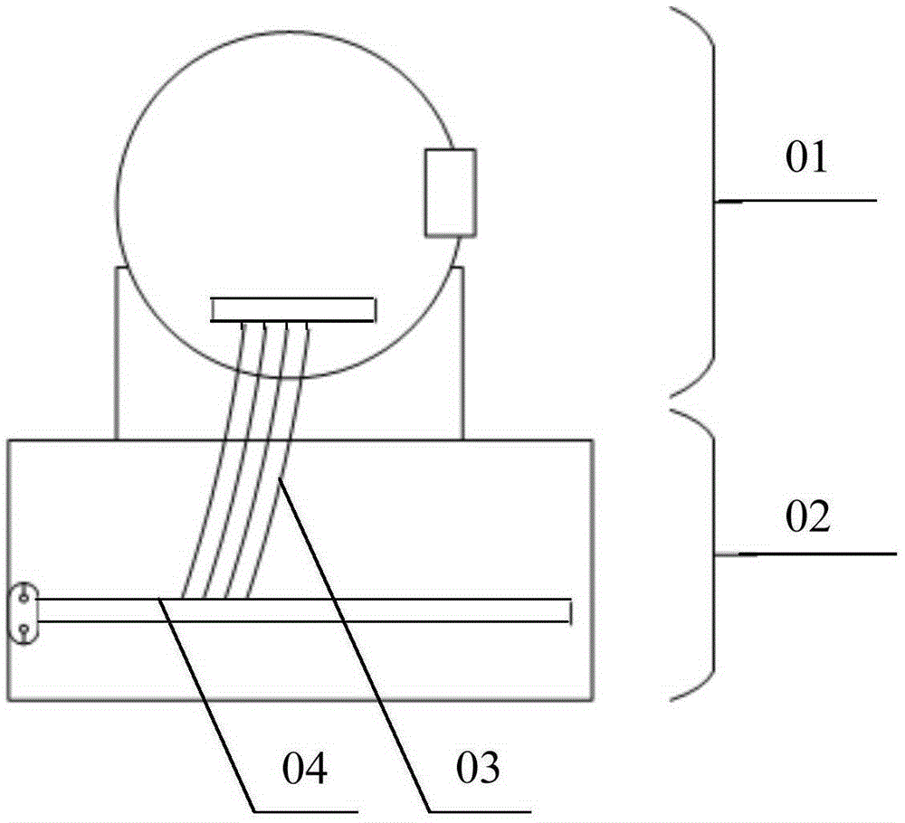
[0024] The core of the present invention is to provide a rotating power supply device, which effectively solves the problem that the rotating part cannot rotate 360 ​​degrees infinitely.

[0025] The following will clearly and completely describe the technical solutions in the embodiments of the present invention with reference to the accompanying drawings in the embodiments of the present invention. Obviously, the described embodiments are only some, not all, embodiments of the present invention. Based on the embodiments of the present invention, all other embodiments obtained by persons of ordinary skill in the art without making creative efforts belong to the protection scope of the present invention.

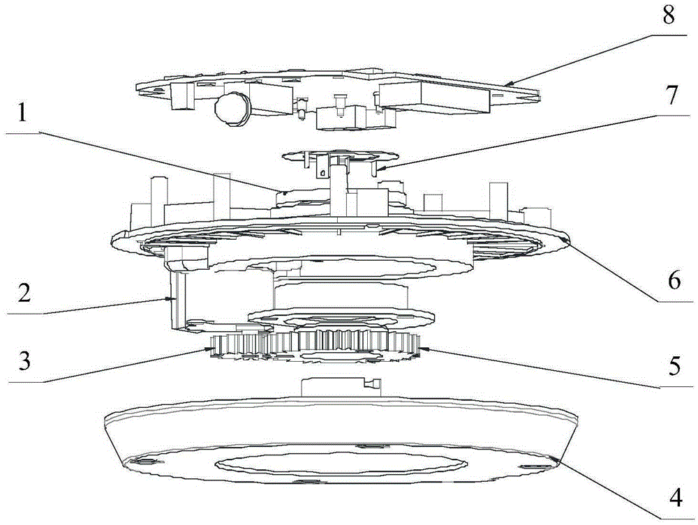
[0026] Please refer to figure 2 , figure 2 It is a schematic structural diagram of a rotating power supply device provided by a specific embodiment of the present invention.

[0027] In a specific embodiment, the rotary power supply device provided by the present inventi...


PUM


Abstract

The invention discloses a rotary power supply device. The rotary power supply device comprises a fixed part of which position is fixed, and a rotary part which can rotate 360 degrees around the fixed part; the fixed part is provided with a first electric conductor communicated with an anode of a power supply and a second electric conductor (7) communicated with a cathode of the power supply; a third electric conductor communicated with the anode and a fourth electric conductor communicated with the cathode are connected on a circuit board (8) in the rotary part; and the rotary part rotates around the fixed part and then drives the third electric conductor to be in slide contact with the first electric conductor and drives the fourth electric conductor to be in slide contact with the second electric conductor (7). The rotary power supply device provided by the invention effectively solves the problem that the rotary part cannot infinitely rotate 360 degrees.

Description

technical field [0001] The invention relates to the technical field of rotating equipment, in particular to a rotating power supply device. Background technique [0002] Please refer to figure 1 , figure 1 It is a structural schematic diagram of a typical cloud platform in the prior art. The existing pan / tilt network camera can only remotely control the horizontal rotation of about 300 to 355 degrees. There are multiple connecting wires 03 and power lines between the rotating part 01 and the fixed part 02 of the pan / tilt. The circuit board 04 is arranged on the fixed part 02 Inside. The internal rotating part 01 of the camera has a convex point, which will touch the micro switch when it rotates to 0 degrees or 355 degrees. After the software detects, the control motor stops rotating and can only rotate in the opposite direction. The rotating part 01 cannot achieve 360-degree infinite rotation, otherwise the connecting line 03 will be stirred into multiple turns until it ...

Claims


Application Information

Patent Timeline
Patent Type & Authority Applications(China)
IPC IPC(8): H01R35/00
Inventor 程宇航章魁
Owner 上海青芒智能科技有限公司
Why Eureka
Try Eureka