Check patentability & draft patents in minutes with Patsnap Eureka AI!

Magnetic shielding device for shaft-diameter-cut multi-directional evacuation flux leakage at the end of turbogenerator

A technology of turbo generator and shielding device, which is applied in the direction of shielding electromagnetic fields, etc., and can solve the problems that the effective dispersion of magnetic flux leakage at the end of the generator cannot be achieved.

Inactive Publication Date: 2017-11-21
HARBIN UNIV OF SCI & TECH
View PDF8 Cites 0 Cited by
  • Summary
  • Abstract
  • Description
  • Claims
  • Application Information

AI Technical Summary

Problems solved by technology

[0003] In order to suppress the influence of the parasitic magnetic flux leakage at the end on the stator core and other metal structural parts, the end of the existing large-capacity turbogenerator usually adopts a magnetic shunt structure to simply suppress the magnetic flux leakage. For the existing turbogenerator The magnetic shielding at the end of the machine is formed by punching the magnetically conductive silicon steel sheet into a circular ring and laminating it along the axial direction. However, this single type of shielding is only a simple shielding of the local leakage field at the end. Many structures at the end of the generator, such as baffles and stator casings, will still be violated by the leakage flux at the end, and the existing simple independent radial-tangential shielding at the end of the generator cannot achieve protection against the generator. Effective dispersion of magnetic flux leakage at the end, so the present invention proposes a magnetic shielding device for shaft-diameter-cut multi-directional cooperative evacuation of magnetic flux leakage at the end of the turbogenerator

Method used


Image

  • Magnetic shielding device for shaft-diameter-cut multi-directional evacuation flux leakage at the end of turbogenerator
  • Magnetic shielding device for shaft-diameter-cut multi-directional evacuation flux leakage at the end of turbogenerator
  • Magnetic shielding device for shaft-diameter-cut multi-directional evacuation flux leakage at the end of turbogenerator

Examples


specific Embodiment approach 1

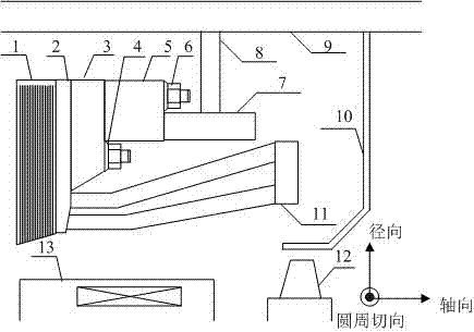
[0017] Specific implementation mode one: combine Figure 1-8 Describe this embodiment, the shaft-diameter-cut multi-directional cooperative magnetic shielding device for evacuating magnetic flux leakage at the end of the turbogenerator in this embodiment needs to add an axial-radial magnetic shielding device (7) at the end of the generator , realize the integration of the axial-radial magnetic shielding device (7) and the traditional radial-tangential magnetic shielding device (3), and evacuate the generator magnetic flux leakage from multiple directions, so as to prevent the iron core (1) at the end of the stator And the stator casing (9) and the end baffle cover (10) are disturbed by the end parasitic magnetic flux leakage.

specific Embodiment approach 2

[0018] Specific implementation mode two: combination Figure 1-3 Describe this embodiment, the shielding device (3) of radial-tangential magnetization at the end of the generator described in this embodiment mainly absorbs the path from the rotor side (13) in the end area to the core (1) at the end of the stator The leakage flux on the generator end shaft-radial magnetic shielding device (7) is used to absorb the annular magnetic flux leakage generated by the stator end winding (11) in the end space when the generator is running; the end shaft - The shielding device (7) for radial magnetic conduction is arranged on the outer side of the stator end winding (11), at a certain distance from the stator casing (9) and the end baffle cover (10). The axial-radial magnetically conductive shielding device (7) guides the annular magnetic flux leakage generated by the stator end winding (11), and also plays a role in evacuating the radial-tangential magnetically conductive shielding devi...

specific Embodiment approach 3

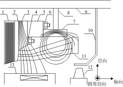
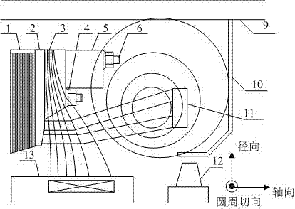
[0019] Specific implementation mode three: combination figure 2 , 4 5. Describe this embodiment. The axial-radial magnetically permeable shielding device (7) added at the end of the generator described in this embodiment is formed by stacking rectangular cold-rolled silicon steel sheets (14) along the circle. There is a rectangular hole (19) in the middle of the punched sheet of the rolled silicon steel sheet (14), and through the rectangular hole (19), the rectangular cold-rolled silicon steel sheet (14) is inserted one by one along the circumferential direction into the ring rod (15) with a certain gap. ), after the set is completed, seal the gaps at both ends of the ring rod (15) with sleeves, and each rectangular cold-rolled silicon steel sheet (14) has a binding opening (20) at the corner, through which the binding opening (20) Insert metal binding strips to compress each stacked segment, and then install the axial-radial magnetic shielding device (7) on the outer side ...


PUM


Abstract

The invention discloses a shaft-diameter-cut multi-directional cooperative magnetic shielding device for evacuating magnetic flux leakage at the end of a turbogenerator, which aims to plan the distribution of magnetic flux leakage at the end by utilizing the characteristics of low magnetic resistance and anisotropy of the shield, Solve the problem of unreasonable accumulation of magnetic flux leakage at the end of the generator. The complex structure and current distribution of the generator stator end directly lead to a very complicated distribution of magnetic flux leakage at the end. By setting soft magnetic silicon steel with different stacking directions at the end of the turbogenerator, the complex distribution of parasitic magnetic flux leakage at the end of the generator is realized. Through timely and effective multi-directional evacuation, the joint suppression of leakage flux entering the iron core and the effect of inducing large eddy currents in the casing and end baffles to cause local overheating of structural parts can ensure the safety of the end structure of large-capacity turbogenerators. long term health. This multi-directional shielding device for evacuating magnetic flux leakage greatly improves the protection degree of the stator end structure of the generator, and avoids adverse hazards such as force vibration and thermal deformation of the stator end structure and the occurrence of malignant accidents.

Description

technical field [0001] The invention relates to the technical field of motors, and belongs to the field of electrical engineering, in particular to a magnetic shielding device for shaft-diameter-cut multi-directional evacuation of magnetic flux leakage at the end of a turbogenerator. Background technique [0002] With the continuous improvement of the capacity of the turbogenerator, its electromagnetic load increases sharply. Due to the complex structure of the end area of ​​the turbogenerator, the distribution of electric density at the end is also very complicated, which will lead to a complex distribution of magnetic flux leakage and a magnetic load at the end of the generator. Increase, since the magnetic flux leakage at the end of the generator is a useless parasitic magnetic field, how to effectively shield the magnetic flux leakage at the end of the generator has always been a technical problem that plagues the electrical engineering and academic circles. The magnetic ...

Claims


Application Information

Patent Timeline
Patent Type & Authority Patents(China)
IPC IPC(8): H02K11/01
Inventor 王立坤戈宝军寇宝泉孙玉田陶大军张赫张鲁
Owner HARBIN UNIV OF SCI & TECH
Features
  • R&D
  • Intellectual Property
  • Life Sciences
  • Materials
  • Tech Scout
  • Unparalleled Data Quality
  • Higher Quality Content
  • 60% Fewer Hallucinations
Learn More