Joining device for resin member, joining structure, and joining method

A technology for joining devices and components, which is applied to household components, other household appliances, household appliances, etc., can solve the problems of heating energy waste, heating time consumption, etc.

Inactive Publication Date: 2015-12-23
NEWFREY
View PDF3 Cites 16 Cited by
  • Summary
  • Abstract
  • Description
  • Claims
  • Application Information

AI Technical Summary

Problems solved by technology

However, when joining, the resin parts are heated by Joule heat, so the heating takes time, and the heating energy is largely wasted due to heating over a wide area.

Method used


Image

  • Joining device for resin member, joining structure, and joining method
  • Joining device for resin member, joining structure, and joining method
  • Joining device for resin member, joining structure, and joining method

Examples


no. 1 approach

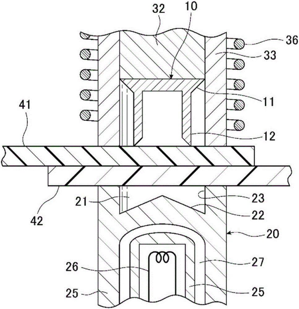
[0094] figure 1 It is a cross-sectional view of the bonding device 1 according to the first embodiment of the present invention. The joining device 1 superimposes the resin parts 41 and 42 and heats the self-piercing rivet 10 by high-frequency electromagnetic induction heating. While the resin parts 41 and 42 are melted, the self-piercing rivet 10 is driven in, and the self-piercing rivet 10 is passed through the self-piercing rivet 10. The driving of the resin and the fusion of the resin members 41 and 42 are joined.

[0095] The joining device 1 has a mold 20 that receives a self-piercing rivet 10. The mold 20 has an inner cavity 21 for receiving the foot 12 of the self-piercing rivet 10 thereon. The cavity 21 has a conical conical surface 22 whose height decreases from the axial center to the outer periphery, and a side surface 23 surrounding the conical surface 22. The inner cavity 21 of the mold 20 accommodates the resin members 41 and 42 and is molded, and the tip of the ...

no. 2 approach

[0135] Figure 7 It is a cross-sectional view showing a state where the resin members 41 and 42 are joined by the self-piercing rivet 50 of the second embodiment. The second embodiment is different from the first embodiment in the shape of the self-piercing rivet 50 and the cavity of the mold. The other parts of the joining device 1 are the same as in the first embodiment. The self-piercing rivet 50 of the second embodiment has a head 51 and a leg 52. When the resin members 41 and 42 are joined by the self-piercing rivet 50, the tip portion of the leg 52 of the self-piercing rivet 50 penetrates the resin members 41, 42 and the part protruding from the lower surface of the resin member 42 is enlarged to increase the diameter of the resin member 41 and 42 join.

[0136] The self-piercing rivet 50 is heated by high-frequency electromagnetic induction. The vicinity of the interface between the resin members 41 and 42 near the leg 52 of the self-piercing rivet 50 is heated to softe...

no. 3 approach

[0141] Picture 9 It is a perspective view of a self-piercing rivet 60 according to the third embodiment of the present invention. The third embodiment is different from the second embodiment in the shape of the self-piercing rivet 60 and the cavity of the mold. The self-piercing rivet 60 is a U-shaped nail-shaped mold, that is, a U-shaped mold with a rectangular cross section, and has a head 61 and two legs 62. The inner cavity of the mold has a shape such as a receiving portion of a stapler, and has a shape capable of bending the two leg portions 62 inward.

[0142] Picture 10 It is a cross-sectional view showing a state where the resin members 41 and 42 are joined using a self-piercing rivet 60. The self-piercing rivet 60 is driven from above the upper resin member 41, and the two leg portions 62 penetrate the upper resin member 41 and the lower resin member 42 and protrude from the lower surface of the lower resin member 42.

[0143] The self-piercing rivet 60 is heated by h...


PUM


Abstract

A joining device whereby damage to a resin member is unlikely to occur when joining a plurality of resin members by using a self-piercing rivet. The joining device (1) a punch (31) to punch and join the self-piercing rivet (10) to the plurality of resin members (41, 42) arranged upon a die (20). The joining device (1) comprises: a die that receives a resin member and a leg section (12) of the self-piercing rivet; a die support member (25) comprising an insulating body, for supporting the die; a high-frequency electromagnetic induction coil (26) arranged inside the die support member; a pre-clamp (33) comprising an insulating body, for fixing the resin member on the die; a high-frequency electromagnetic induction coil (36) wound around the pre-clamp; and the punch (31) comprising an insulating body, for punching the self-piercing rivet. The plurality of resin members are joined by the punching of the self-piercing rivet and the fusing of the plurality of resin members.

Description

Technical field [0001] The present invention relates to a coupling device, a coupling structure and a coupling method for coupling a plurality of resin components. In particular, it relates to a joining device, a joining structure, and a joining method for driving a self-piercing rivet from the uppermost resin member to fuse and join the resin members. Background technique [0002] When joining parts to each other, there is a method of using self-piercing rivets. The self-piercing rivet-based joining method places two parts (metal plates) on a mold with an inner cavity formed thereon, and positions the self-piercing rivet with a large diameter head and a foot extending from the head On the upper part. If the self-piercing rivet is driven into the component with a punch, the foot of the self-piercing rivet penetrates the upper part, and the foot enters the lower part and expands. By driving the self-piercing rivet, the upper part and the lower part are plastically deformed in t...

Claims


Application Information

Patent Timeline
Patent Type & Authority Applications(China)
IPC IPC(8): B21J15/00B21J15/30B29C65/36
CPCB21J15/025B21J15/08B21J15/147B21J15/36B29C65/3604B29C65/3676B29C65/46B29C65/562B29C66/1122B29C66/21B29C66/43B29C66/71B29C66/721B29C66/7212B29C66/7392B29C66/81431B29C66/81811B29C66/8322B29L2031/7288B29K2023/06B29K2023/12B29K2055/02B29K2069/00B29K2077/00B29K2307/04
Inventor 近藤吉辉铃木晴彦松平义道中神英治今泉博司
Owner NEWFREY
Why Eureka
Try Eureka