
Capitulum radius replacement prosthesis

A small head and radius technology, applied in the field of radial head replacement prosthesis, can solve the problem of unreasonable bone cement composition of radial head replacement prosthesis, affecting initial stability and joint stability, affecting elbow joint stability and Safety and other issues, to achieve the effect of reasonable force, high long-term use stability, and simple structure

Active Publication Date: 2015-12-30
北京威高亚华人工关节开发有限公司
View PDF6 Cites 2 Cited by
  • Summary
  • Abstract
  • Description
  • Claims
  • Application Information

AI Technical Summary

Problems solved by technology

However, there is still a lack of radial head replacement prostheses that can be satisfactorily compatible with the body and firmly integrated with the body, and have a high success rate and satisfactory effect, and can be used for surgical repair and implantation.
[0003] The existing radial head replacement prosthesis completely refers to the anatomical shape of the human radial head, which includes the radial head and the radial needle. Although it conforms to the daily behavior and movement characteristics of the human body, the radial head replacement prosthesis generally has the following technical problems : (1) Due to the defects of the connector structure affecting the initial stability and joint stability, and then causing postoperative loosening, infection and instability (subluxation or dislocation) and other complications; (2) Radial head replacement prosthesis Unreasonable components of bone cement affect the stability and safety of the postoperative elbow joint

Method used


Image

  • Capitulum radius replacement prosthesis
  • Capitulum radius replacement prosthesis
  • Capitulum radius replacement prosthesis

Examples


Embodiment 1

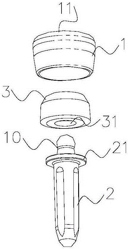
[0028] figure 1 It is a structural schematic diagram of Embodiment 1 of the present invention. Specific as figure 1 As shown, the radial head replacement prosthesis in Example 1 includes a radial head 1 and a radial pin 2, the radial head 1 is in the shape of a truncated cone, and the end surface of the large diameter end of the radial head 1 is used as an articular surface and is formed by inward depression. Spherical crown-shaped joint cavity 11, the spherical center of which is located on the axis of the radial medullary needle 2; the end of the radial medullary needle 2 is provided with a connecting plane 21, the connecting plane 21 is circular and its diameter is the same as that of the radial head The diameters of the small-diameter ends of 1 are the same, and the small-diameter end of the radial head 1 is connected to the connecting plane 21 of the radial medullary needle 2 through a connecting piece.

[0029] The connector in the present embodiment is the indenter 10...

Embodiment 2

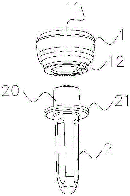
[0033] figure 2 It is a structural schematic diagram of Embodiment 2 of the present invention. Specific as figure 2 As shown, the radial head replacement prosthesis in Example 2 includes the radial head 1 and the radial needle 2, the radial head 1 is in the shape of a truncated cone, and the end surface of the large diameter end of the radial head 1 is used as the articular surface and is formed by inward depression. Spherical crown-shaped joint cavity 11, the spherical center of which is located on the axis of the radial medullary needle 2; the end of the radial medullary needle 2 is provided with a connecting plane 21, the connecting plane 21 is circular and its diameter is the same as that of the radial head The diameters of the small-diameter ends of 1 are the same, and the small-diameter end of the radial head 1 is connected to the connecting plane 21 of the radial medullary needle 2 through a connecting piece.

[0034] The connector in this embodiment is a connector ...

Embodiment 3

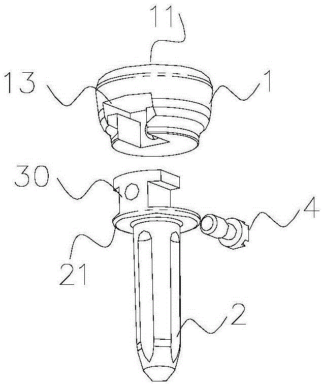
[0037] image 3 It is a structural schematic diagram of Embodiment 3 of the present invention. Specific as image 3As shown, the radial head replacement prosthesis in Example 3 includes the radial head 1 and the radial needle 2, the radial head 1 is in the shape of a truncated cone, and the end surface of the large diameter end of the radial head 1 is used as the articular surface and is formed by inward depression. Spherical crown-shaped joint cavity 11, the spherical center of which is located on the axis of the radial medullary needle 2; the end of the radial medullary needle 2 is provided with a connecting plane 21, the connecting plane 21 is circular and its diameter is the same as that of the radial head The diameters of the small-diameter ends of 1 are the same, and the small-diameter end of the radial head 1 is connected to the connecting plane 21 of the radial medullary needle 2 through a connecting piece.

[0038] The connector in this embodiment is a plug 30, whic...


PUM


Abstract

The invention provides a capitulum radius replacement prosthesis. The capitulum radius replacement prosthesis comprises a capitulum radius and a radius broach, wherein the capitulum radius is in the shape of a circular truncated cone, the end face of the large-diameter end of the capitulum radius serves as the articular surface and is sunk inwards to form a spherical articular cavity, and the sphere center of the spherical articular cavity is located on the axis of the radius broach; a round connecting plane is arranged at the end of the radius broach, the diameter of the connecting plane is identical with that of the small-diameter end of the capitulum radius, and the small-diameter end of the capitulum radius is connected with the connecting plane of the radius broach through a connecting part in a matched mode. The capitulum radius replacement prosthesis accords with human anatomy and daily performance kinetic characteristics and has high stability and safety. Through the improvement of bone cement constituents, biocompatibility between the capitulum radius replacement prosthesis and bone substances is improved, complications such as deviation, looseness, infection and instability do not occur easily, service life is long, and different connecting parts can be adopted according to the conditions of patients to guarantee the optimal using effect of the capitulum radius replacement prosthesis.

Description

technical field [0001] The invention relates to the field of orthopedic implant technology, in particular to a radial head replacement prosthesis. Background technique [0002] For patients with radial head defects or lesions caused by various reasons such as trauma and tumor removal, generally only by implanting the radial head replacement prosthesis and making it compatible and organically combined with the surrounding tissues of the elbow, after After functional training, it is possible to restore the normal function of the elbow joint. However, there is still a lack of radial head replacement prosthesis that can be satisfactorily compatible and firmly integrated with the body, and has a high success rate and satisfactory effect, which can be used for surgical repair and implantation. [0003] The existing radial head replacement prosthesis completely refers to the anatomical shape of the human radial head, which includes the radial head and the radial needle. Although i...

Claims


Application Information

Patent Timeline
Patent Type & Authority Applications(China)
IPC IPC(8): A61F2/30
CPCA61F2/42A61F2002/30001
Inventor 于刚史树奎刘博吕心建
Owner 北京威高亚华人工关节开发有限公司
Learn More