
electric screwdriver

An electric screwdriver and drive shaft technology, applied in the field of power tools, can solve the problems of large jumping and shaking, large jumping and shaking, etc.

Active Publication Date: 2017-10-10
POSITEC POWER TOOLS (SUZHOU) CO LTD
View PDF5 Cites 0 Cited by
  • Summary
  • Abstract
  • Description
  • Claims
  • Application Information

AI Technical Summary

Problems solved by technology

However, since the cross-section of the drive shaft is not circular, the jump and shake generated when it cooperates with the gear will be relatively large. In addition, there will also be relatively large jump and shake between the drive shaft and the bearing supporting the drive shaft.

Method used


Image

  • electric screwdriver
  • electric screwdriver
  • electric screwdriver

Examples


Embodiment Construction

[0032] In order to facilitate the understanding of the present invention, the present invention will be described more fully below with reference to the associated drawings. Preferred embodiments of the invention are shown in the accompanying drawings. However, the present invention can be embodied in many different forms and is not limited to the embodiments described herein. On the contrary, these embodiments are provided to make the understanding of the disclosure of the present invention more thorough and comprehensive.

[0033] It should be noted that when an element is referred to as being “fixed” to another element, it can be directly on the other element or there can also be an intervening element. When an element is referred to as being "connected to" another element, it can be directly connected to the other element or intervening elements may also be present. In contrast, when an element is referred to as being "directly on" another element, there are no interveni...


PUM


Abstract

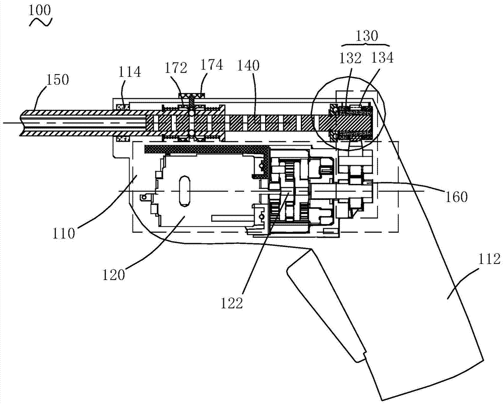
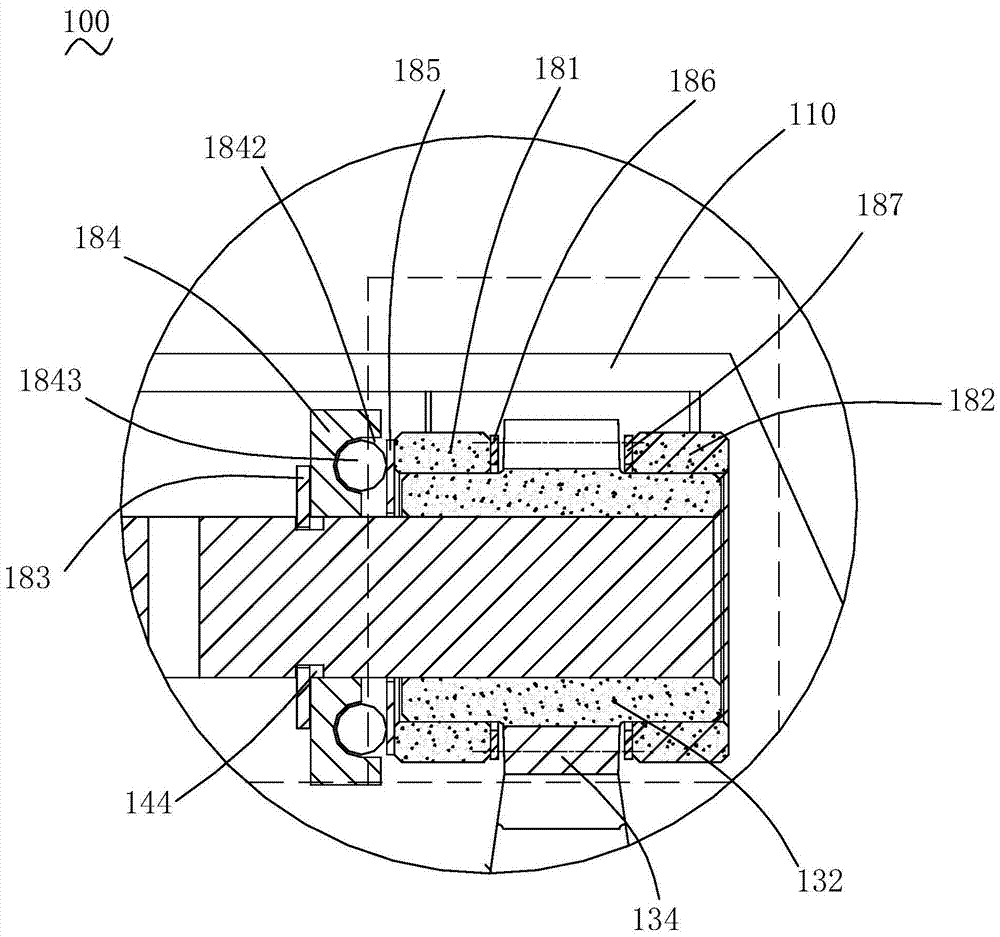
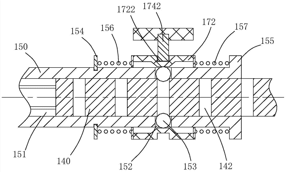
The invention relates to an electric screwdriver, which comprises a casing, a motor arranged in the casing, and a drive shaft protruding from the front of the casing, and a transmission gear driven by the motor, a driving The transmission shaft of the drive shaft, the transmission shaft is closely matched with the transmission gear, the motor is closer to the front of the casing than the transmission gear, and the drive shaft is retractable relative to the transmission shaft It is provided that the front part of the casing is also provided with a front bearing supporting the drive shaft, and the front bearing and the drive shaft are fitted with a circular surface. The above-mentioned electric screwdriver, the motor is arranged at the front of the casing, and the transmission gear is arranged at the rear. The transmission shaft and the transmission gear are tightly fitted. It has a round fit with the front bearing that supports it, which can reduce jumping and shaking.

Description

technical field [0001] The invention relates to the technical field of power tools, in particular to a hand-held electric screwdriver. Background technique [0002] A traditional electric screwdriver generally includes a casing, a motor and a gear system arranged in the casing, and a drive shaft protrudes from the casing to drive the screwdriver head to work. For this kind of electric screwdriver, the motor is arranged at the rear of the casing, and the gear system is arranged at the front of the casing. The gears of the gear system are in clearance fit, so that the gears can drive the drive shaft, and at the same time, the drive shaft has the function of telescoping. But because the cross-section of the drive shaft is not circular, the jump and shaking generated when it cooperates with the gear will be relatively large. In addition, there will be relatively large jump and shake between the drive shaft and the bearing supporting the drive shaft. Contents of the invention ...

Claims


Application Information

Patent Timeline
Patent Type & Authority Patents(China)
IPC IPC(8): B25B21/00
Inventor 陈志杜祥金
Owner POSITEC POWER TOOLS (SUZHOU) CO LTD
Learn More