Clamping device for easily detachable spindle base

A technology of clamping device and sub-spindle, which is applied in the direction of chucks, manipulators, manufacturing tools, etc., can solve the problems of waste, high labor intensity, low production efficiency, etc., and achieve the effect of reducing production costs and energy consumption

Inactive Publication Date: 2017-01-11
衡阳新新纺织机械有限公司
View PDF6 Cites 0 Cited by
  • Summary
  • Abstract
  • Description
  • Claims
  • Application Information

AI Technical Summary

Problems solved by technology

The dismantling fixture of the spindle seat with a cone and outer circle is not suitable for the disassembly of the spindle seat with a straight outer circle, because the dismantling fixture cannot clamp the straight outer circle of the bearing seat tightly, and the production and processing cycle of the jig base is long. When the fixture is worn out, the entire fixture base must be replaced, resulting in a lot of waste; while the bearing seat is a straight outer circle spindle seat, the current split method requires drilling and piercing the mandrel, the processing procedures are complicated, and can only be used Due to manual operation, its production efficiency is low and the labor intensity is high, so it is not suitable for batch pulling out of ingots

Method used


Image

  • Clamping device for easily detachable spindle base
  • Clamping device for easily detachable spindle base
  • Clamping device for easily detachable spindle base

Examples


Embodiment 1

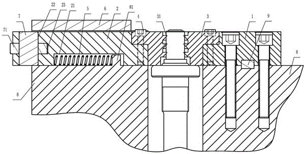
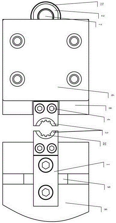
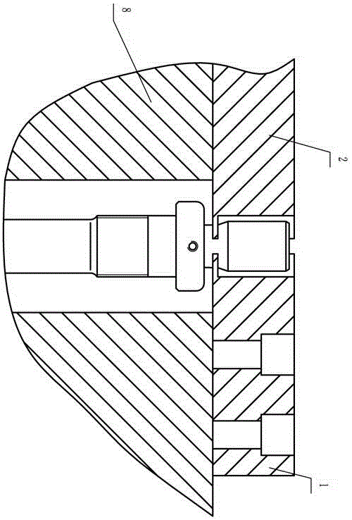
[0033] Such as figure 1 , figure 2 As shown, a clamping device for an easy-to-split spindle base, which includes a right base 1, a left base 2 and a jacket, the right base 1 and the left base 2 are rectangular parallelepiped and symmetrically arranged, and the right base 1 is fixed on the base of the press 8; the jacket includes two symmetrically arranged semi-circular jacket blocks 3, the jacket blocks 3 are symmetrically fixed on the right base 1 and the left base 2 respectively by bolts 4, when the two jacket blocks 3 are closed, it forms The inner hole of the inner hole can clamp the bearing seat of the ingot liner. The inner surface of the jacket block 3 is axially provided with three radial ring teeth 31 with a trapezoidal cross section. The front end of the trapezoidal teeth is thin and the rear end is thick, so that the ring teeth can bite into On the outer circle of the bearing housing, the radial annular teeth 31 are provided with axial grooves 32 to ensure that t...


PUM


Abstract

The invention discloses a clamping device with a spindle pedestal easy to disassemble. The clamping device with the spindle pedestal easy to disassemble comprises a right substrate 1, a left substrate 2 and a jacket, the right substrate 1 and the left substrate 2 are shaped like cuboids and symmetrically arranged, and the right substrate 1 is fixed on a press base 8; the jacket comprises two symmetrically arranged semicircular-ring-shaped jacket blocks 3 which are symmetrically fixed on the right substrate 1 and the left substrate 2 respectively through bolts 4, the inner surface of each jacket block 3 is axially provided with radial annular teeth 31 of which the cross section is shaped like a trapezoid, a strip-shaped groove 21 is formed in the contact surface of the left substrate 2 and the base 8, a boss 81 is arranged on the portion, corresponding to the strip-shaped groove 21, of the base 8, a spring 5 is installed between the boss 81 and the strip-shaped groove 21, motion of the left substrate 2 in the vertical direction is limited by a pressing plate 6, and the pressing plate 6 is connected with the base 8 through a bolt. The clamping device with the spindle pedestal easy to disassemble has the advantages that the jacket blocks are replaceable, the clamping device is suitable for disassembling of the spindle pedestal of bearing seats with different external diameters and bearing seats with different shapes, and meanwhile automation of disassembling of the spindle pedestal can be achieved.

Description

technical field [0001] The invention relates to a clamping device, in particular to a clamping device for an easily detachable spindle seat. Background technique [0002] The ingot base of the spindle includes the ingot core and the ingot foot. The ingot core is pressed in the ingot foot. During the production process of the ingot base, there are often a certain proportion of unqualified products. Generally, the unqualified ingot base will be inspected. Separate disassembly, pull out the ingot core from the ingot seat, recycle the ingot foot and other usable parts inside, and only scrap the ingot core, thereby reducing production costs. There are two existing methods for splitting the spindle base: image 3 As shown, for the bearing seat of the ingot gallbladder containing the ingot seat of the cone outer circle, the method of pulling out the ingot seat is to fix the base 8 through the right base 1 and the left base 2, the left part of the base 8 does not move, and the base ...

Claims


Application Information

Patent Timeline
Patent Type & Authority Patents(China)
IPC IPC(8): B25J15/10
Inventor 黄喜芝彭来深
Owner 衡阳新新纺织机械有限公司
Why Eureka
Try Eureka