Forming device for bellows

A technology of forming device and bellows, applied in the direction of tubular articles, other household appliances, household appliances, etc., can solve the problems of large investment, unguaranteed quality, poor roundness of bellows, etc.

Active Publication Date: 2017-12-19
SICHUAN GOLDSTONE ORIENT NEW MATERIAL TECH CO LTD
View PDF7 Cites 0 Cited by
  • Summary
  • Abstract
  • Description
  • Claims
  • Application Information

AI Technical Summary

Problems solved by technology

Similar forming devices generally exist. When the size of the forming device is large (that is, when a large bellows needs to be manufactured), the size of the main support roll and the support structure are correspondingly large, and the column is only on the main support roll and support. One end of the structure is supported, and the other end of the main support roller and the support structure is inclined downward due to gravity, which causes the forming device to fail to meet the process requirements for producing large-sized corrugated pipes, and causes corrugations formed by this type of forming device The roundness of the tube is poor, and the quality cannot be guaranteed
In addition, similar forming devices also have the problem that each set of corrugated pipes can only produce one specification. need to invest a lot of money

Method used


Image

  • Forming device for bellows
  • Forming device for bellows
  • Forming device for bellows

Examples


Embodiment Construction

[0053] Specific embodiments of the present invention will be described in detail below in conjunction with the accompanying drawings. It should be understood that the specific embodiments described here are only used to illustrate and explain the present invention, and are not intended to limit the present invention.

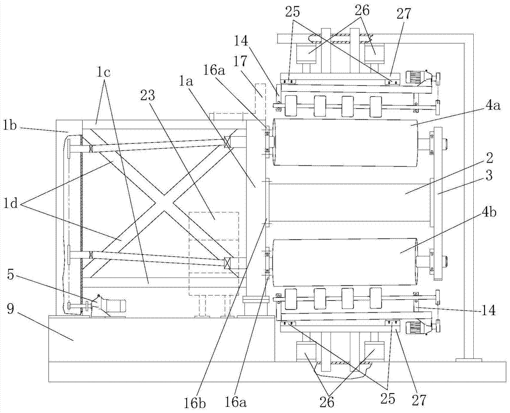
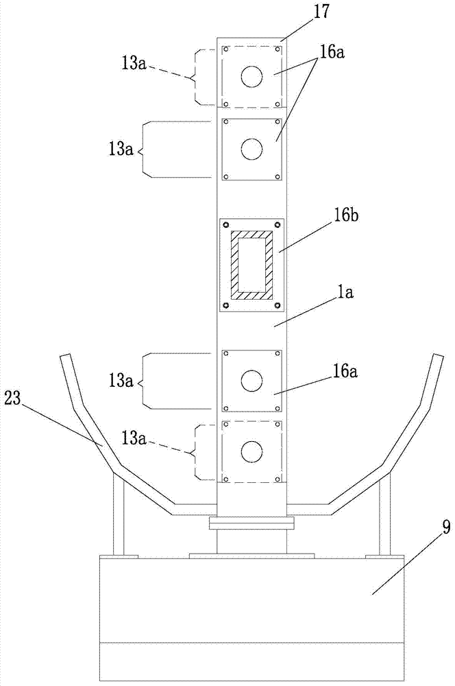
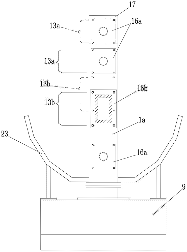
[0054]see Figure 1-Figure 6 , The corrugated tube forming device of the present invention includes: a first bracket 1a, the first bracket 1a is fixed to the frame 9; a main beam 2, one end of the main beam 2 is installed on the first side of the first bracket 1a, The other end of the main beam 2 is provided with an end plate 3; a driving roller, one end of which is pivotally connected to the first bracket 1a, and the other end of the driving roller is pivotally connected to the End plate 3; drive system 5, the drive system 5 is connected with the transmission of the driving roller, the forming device also includes an auxiliary bracket fixed on the frame 9, the...


PUM


Abstract

The invention discloses a corrugated pipe forming device which comprises a first support (1a), a main cross beam (2), a driving roller and a driving system (5). The first support (1a) is fixed to a machine frame (9), one end of the main cross beam (2) is installed on the first side of the first support (1a), the other end of the main cross beam (2) is provided with an end plate (3), one end of the driving roller is connected to the first support (1a) in a pivoted mode, the other end of the driving roller is connected to the end plate (3) in a pivoted mode, the driving system (5) is in transmission connection with the driving roller, and the distance between the center axis of the driving roller and the center axis of the main cross beam (2) can be adjusted. Corrugated pipes of various specifications can be manufactured through the corrugated pipe forming device.

Description

technical field [0001] The invention relates to a forming device for bellows. Background technique [0002] The corrugated pipe is usually formed by winding and compounding the molten plastic strip and the corresponding metal profile layer by layer in a spiral manner. The plastic strip can include a plastic inner sheet for joining the inner wall of the metal profile and a plastic inner sheet for bonding Jointed plastic outer sheets, this type of corrugated pipe is widely used in various scenes of social production and life due to its advantages of light weight, high strength, and aging resistance, such as drainage pipes in cities and drainage in residential areas Pipeline. [0003] A typical bellows forming device is disclosed in the patent application with the notification number CN201329670Y, which includes a support frame, a support structure, a fixed main support roll, a movable main support roll, an auxiliary support roll, etc., a support structure and a fixed main sup...

Claims


Application Information

Patent Timeline
Patent Type & Authority Patents(China)
IPC IPC(8): B29D23/00
Inventor 蒯一希
Owner SICHUAN GOLDSTONE ORIENT NEW MATERIAL TECH CO LTD
Why Eureka
Try Eureka