Metallurgical bridge crane

A bridge crane and pin shaft technology, which is applied in the direction of cranes, trolley cranes, load hanging components, etc., can solve problems such as safety accidents, ladle or ladle falling off, beam cracks, etc., to avoid safety accidents and facilitate replacement Effect

Inactive Publication Date: 2015-12-30
BAOSHAN IRON & STEEL CO LTD
View PDF5 Cites 2 Cited by
  • Summary
  • Abstract
  • Description
  • Claims
  • Application Information

AI Technical Summary

Problems solved by technology

Since there is a certain distance between the pin shaft and the ground, it is not easy to observe even if the pin shaft rotates
And once the pin shaft slips out from the assembly hole, the ladle or ladle will fall off, resulting in a safety accident
[0006] (2) Beams and suspension forks are usually manufactured by welding steel plates. Long-term exposure to high-temperature baking and impact loads will cause fatigue damage to the steel plates. For example, cracks will occur on the lower side of the beams, which will also cause the ladle or ladle to fall off.

Method used


Image

  • Metallurgical bridge crane
  • Metallurgical bridge crane
  • Metallurgical bridge crane

Examples


Embodiment Construction

[0033] Below, the structure and working principle of the present invention will be further described in conjunction with the accompanying drawings.

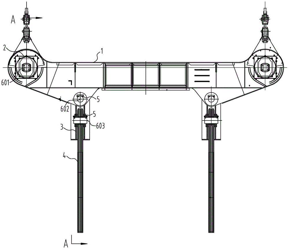
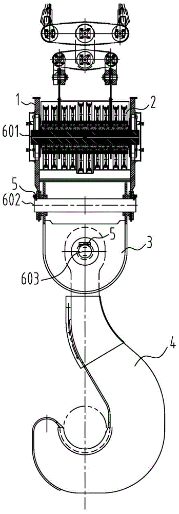
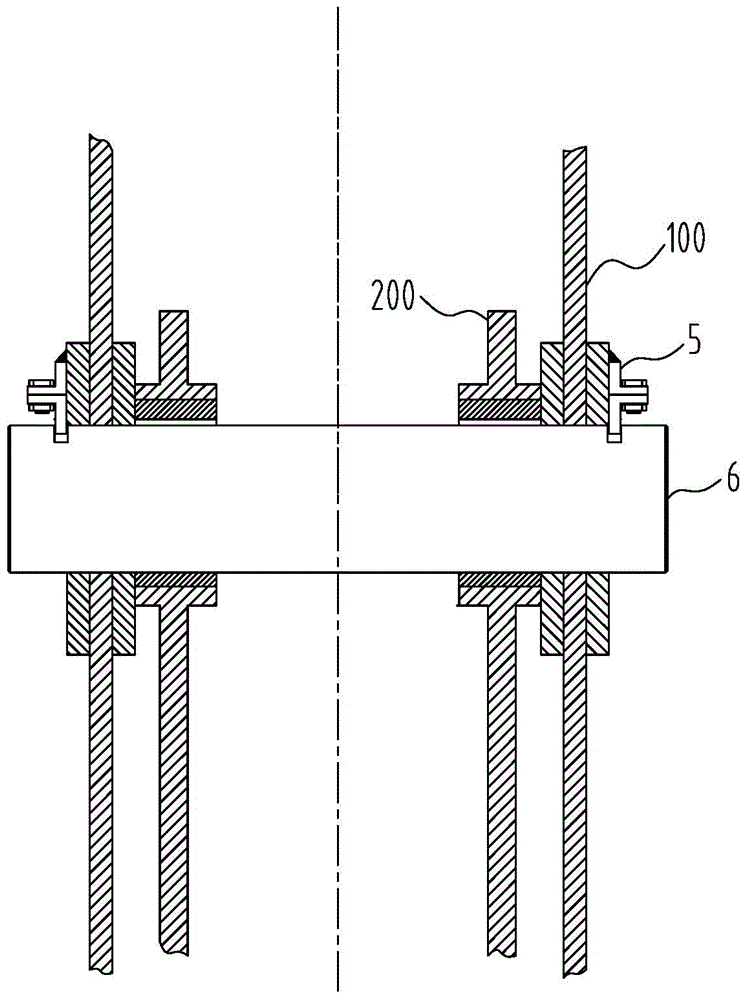
[0034] see Figure 5 ~ Figure 8 , the metallurgical bridge crane of the present invention includes a beam 1, a movable pulley block 2, a suspension fork 3, a suspension hook 4 (a plate hook is shown in the figure) and a plurality of pins 6 for forming hinged joints of two parts, The two parts comprise a first part 100 and a second part 200 located at least partially inside the first part 100 so as to form a hinge with the first part 100 via the pin 6 . Specifically, the two parts include but are not limited to the following situations, the first part 100 is the beam 1, the second part 200 is the moving pulley block 2; the first part 100 is the beam 1, and the second part 200 is the suspension fork 3 ; The first component 100 is the suspension fork 3, and the second component 200 is the suspension hook 4. Of course, this only sho...


PUM


Abstract

The invention discloses a metallurgical bridge crane. The metallurgical bridge crane comprises a cross beam, movable pulley blocks, lifting forks, lifting hooks and a plurality of pin shafts used for hinging two parts. The two parts comprise the first part and the second part which is at least partially located inside the first part so as to be hinged to the first part through the pin shafts. The two ends of each pin shaft extend out of the first part. Grooves are formed in the positions, close to the two ends, of each pin shaft. Baffles used for preventing the pin shafts from being disengaged from the two parts are inserted in the grooves, and the baffles are fixed to the first part. Indicating rods are fixedly arranged at the ends of the pin shafts. By the adoption of the metallurgical bridge crane, the parts can be prevented from being disengaged, and safety accidents are avoided.

Description

technical field [0001] The invention relates to the field of metallurgical equipment, in particular, the invention relates to a metallurgical bridge crane. Background technique [0002] Metallurgical bridge cranes are mainly responsible for the hoisting, feeding, and casting of ladles or ladles in the steelmaking process. The working environment is extremely harsh, with high temperature and dust. As mentioned above, metallurgical bridge cranes are exposed to open flames and subjected to impact loads for a long time during work, which is prone to failure. At the same time, due to the presence of dust in the working environment, it is difficult to find faults even if they exist. [0003] Such as figure 1 , figure 2 As shown, in the prior art, the metallurgical bridge crane includes a beam 1, a movable pulley block 2, a suspension fork 3, a hook 4 and a pin shaft 6, and the number of pin shafts 6 is multiple, such as the first pin mentioned below The shaft 601 , the second ...

Claims


Application Information

Patent Timeline
Patent Type & Authority Applications(China)
IPC IPC(8): B66C19/00B66C15/00
Inventor 王虎亭顾立敏董闽嘉王才良周纯洁施剑涛
Owner BAOSHAN IRON & STEEL CO LTD
Why Eureka
Try Eureka