
Composite foundation construction method

A construction method and composite foundation technology, which is applied in the direction of infrastructure engineering, construction, etc., to achieve the effects of small settlement, convenient construction, and avoiding waste of resources

Inactive Publication Date: 2015-12-30
SICHUAN JIUDINGZHIYUAN INTPROP OPERATIONS CO LTD
View PDF4 Cites 1 Cited by
  • Summary
  • Abstract
  • Description
  • Claims
  • Application Information

AI Technical Summary

Problems solved by technology

[0004] In view of this, the technical problem to be solved by the present invention is to provide a rigid pile composite foundation construction method in order to overcome the shortcomings of the above-mentioned composite foundation construction method. The lateral resistance of the soil, that is, the bearing capacity of the soil between the piles, reduces the number of rigid piles used, so as to save costs and avoid waste of resources

Method used


Image

  • Composite foundation construction method
  • Composite foundation construction method
  • Composite foundation construction method

Examples


Embodiment Construction

[0036] The present invention will be described in detail below in conjunction with the accompanying drawings and embodiments.

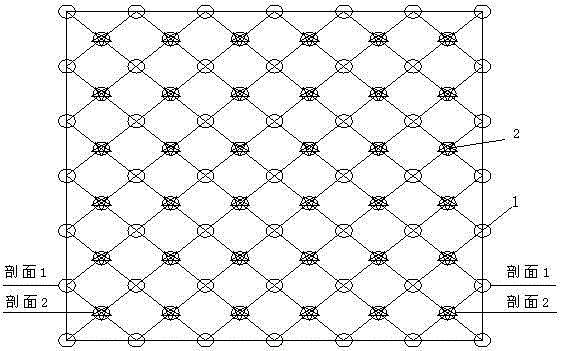
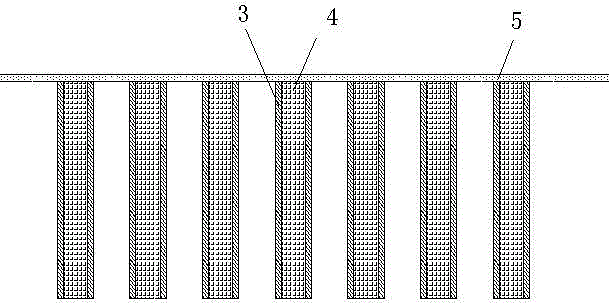
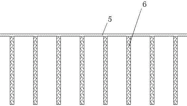
[0037] refer to Figure 1~Figure 3 , the embodiment of the present invention provides a rigid pile composite foundation construction method, comprising the following steps:

[0038] Step 1. Determine the dynamic compaction point in the hole and the rigid pile point in the construction area

[0039] Step 1-1. In the construction area, according to the design requirements, the dynamic compaction point 1 in the hole is evenly arranged, and the interval between any two adjacent dynamic compaction points 2 in the hole is required to be 6~10m; the distance should not exceed this range, if If the interval is smaller than this range, the dynamic compaction in the hole will be too dense, which will not only save the cost, but also cause difficulties in the subsequent rigid pile construction because the soil between the piles is too dense. If the distance is t...


PUM


Abstract

The invention discloses a composite foundation construction method which mainly comprises the following steps: (1) determining rigid pile points and down-hole dynamic compaction points in a construction region; (2) drilling in the down-hole dynamic compaction points and carrying out down-hole dynamic compaction construction; (3) after finishing down-hole dynamic compaction construction, carrying out full-court full compaction; (4) drilling in the rigid pile points, and carrying out rigid pile construction; and (5) after finishing rigid pile construction, and paving a mattress layer on the surface of a construction site, thereby forming a composite foundation. Piles are formed by selecting a long earth auger with small disturbance to soil between the piles; the composite foundation which is good in combination property of rigid piles, flexible piles and the soil between the piles is formed; the collateral resistance of the soil around the piles is put into a full play under the premise of meeting the carrying capacity requirements; the number of the rigid piles is reduced, so that the targets of reducing cost and avoiding resource waste are achieved.

Description

technical field [0001] The invention relates to the technical field of building construction, in particular to a composite foundation construction method. Background technique [0002] At present, in composite foundations, rigid piles bear most of the load, such as CFG piles (abbreviation for CementFly-ashGrave in English, meaning cement fly ash gravel piles), reinforced cage cast-in-place piles, and due to the relatively large diameter of rigid piles Small, can not make full use of the lateral resistance of the soil on the side of the rigid pile pile, in order to meet the requirements of bearing capacity, the distance between the rigid piles has to be reduced, which increases the number of rigid piles used and increases the construction cost. [0003] To sum up, on the premise of meeting the bearing capacity requirements, how to effectively save costs and avoid waste of resources is a technical problem to be solved urgently by those skilled in the art. Contents of the inv...

Claims


Application Information

Patent Timeline
Patent Type & Authority Applications(China)
IPC IPC(8): E02D27/16
Inventor 汪崇营
Owner SICHUAN JIUDINGZHIYUAN INTPROP OPERATIONS CO LTD
Learn More