Roller shutter door lock and working principle thereof

A technology for rolling shutter doors and rolling shutter door motors, which is applied in the field of rolling shutter doors, can solve the problems of manual unlocking, complicated operation steps, and no special door locking device for rolling shutter doors, etc., and achieves the effect of saving installation costs.

Active Publication Date: 2015-12-30
蔡为达
View PDF5 Cites 0 Cited by
  • Summary
  • Abstract
  • Description
  • Claims
  • Application Information

AI Technical Summary

Problems solved by technology

[0003] The invention provides a rolling shutter door lock and its working principle to overcome the disadvantages that the existing rolling door has no

Method used


Image

  • Roller shutter door lock and working principle thereof
  • Roller shutter door lock and working principle thereof
  • Roller shutter door lock and working principle thereof

Examples


Embodiment 1

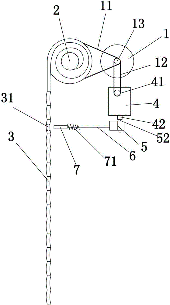
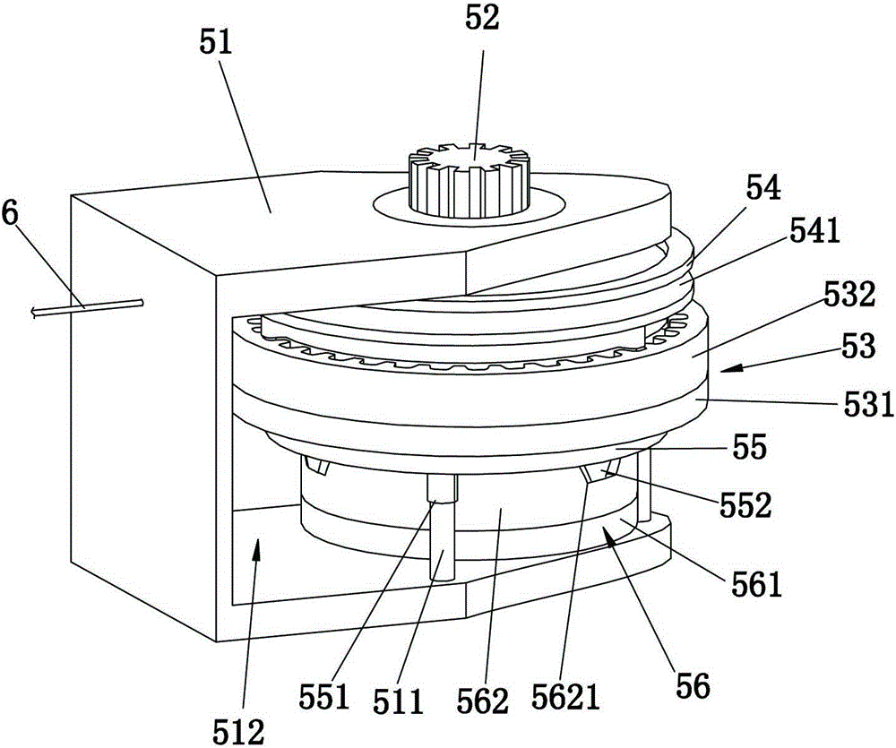
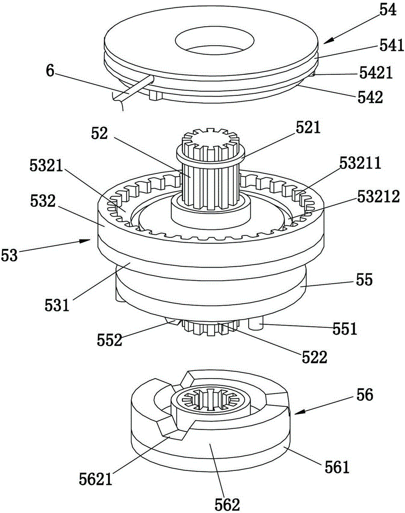
[0029] refer to Figure 1 to Figure 4 , a rolling door lock, comprising a lock core 7 and a spring 71 for moving the lock core 7 toward the rolling door 3 and locking the rolling door 3 . The shutter door lock also includes a cable 6, a clutch device 5 and a motor, wherein the clutch device includes a frame body 51, a rotating shaft 52, a first damping wheel 53, a winding wheel 54, a second damping wheel 56, a return spring (not shown in the figure) out) and disc 55. One end of the cable 6 is connected to the lock cylinder 7 , and the other end is detachably connected to the reel 54 through the through hole in the annular recess 541 . The lock cylinder 7 is a straight rod slidably arranged along its length direction, and the rolling shutter door 3 is provided with a socket 31 matched with the lock cylinder 7 .

[0030] refer to Figure 2 to Figure 4 , the frame body 51 is U-shaped and forms a mounting groove 512 , and at least one cylinder 511 is disposed in the mounting gr...

Embodiment 2

[0040] refer to Figure 5 , the rolling door lock includes a rolling door motor 1 , an acceleration box 4 , a clutch device 5 , a cable 6 , a spring 71 and a lock cylinder 7 . Regarding the specific setting method of the lock core 7, another specific embodiment: the rolling door lock also includes a supporting block 10, a bracket 8 and at least one connecting rod 9, and the lock core 7 is provided with a concave surface 32 that fits the inner side of the rolling door 3. The curved surface 72. One end of the connecting rod 9 is pivotally connected to the bracket 8 , and the other end is pivotally connected to the lock cylinder 7 , and the lock cylinder 7 is located obliquely below the bracket 8 . The supporting block 10 is supported on the outer surface of the rolling door 3 and cooperates with the lock cylinder 7 to clamp the rolling door 3 . When a thief uses a tool to try to pry open the rolling door 3, because the lock core 7 is arranged on the oblique lower side of the s...


PUM


Abstract

The invention discloses a roller shutter door lock and a working principle thereof, and relates to the technical field of roller shutter doors. The roller shutter door lock comprises a lock cylinder, a spring enabling the lock cylinder to move towards a roller shutter door and lock the roller shutter door, an inhaul cable, a clutch device and a motor. One end of the inhaul cable is connected with the lock cylinder, and the other end of the inhaul cable is connected with the clutch device. The clutch device is driven by the motor to roll the inhaul cable, so that the lock cylinder and the roller shutter door are disengaged, and the roller shutter door is unlocked. After the motor stops, the inhaul cable rolled by the clutch device is stretched by the spring, so that the lock cylinder moves towards the roller shutter door, and the roller shutter door is locked. The roller shutter door lock and the working principle thereof have the advantages that additional operation is not needed when the roller shutter door is unlocked or locked, the operation of unlocking or locking the roller shutter door can be completed through the roller shutter door lock as long as the roller shutter door normally ascends and descends, operation is easy, and the anti-theft effect is good.

Description

technical field [0001] The invention relates to the technical field of rolling doors, in particular to a rolling door lock and its working principle. Background technique [0002] The door leaf of the rolling door is a movable door leaf composed of multiple door panels connected in series. The door leaf is rolled up and down to realize the opening and closing of the door. At present, the opening and closing of the rolling door is realized by the rolling door motor set on the rolling door reel. Usually, the rolling door does not have a separate The door lock relies entirely on the self-locking function of the rolling door motor, which is easy to be pried open and has poor anti-theft performance. In order to improve the anti-theft performance of the rolling door, a mechanical lock is usually installed on the door leaf of the rolling door at present. Although the mechanical lock increases the anti-theft performance of the rolling door, manual operation is required for each loc...

Claims


Application Information

Patent Timeline
IPC IPC(8): E05B65/00E05B47/00E06B9/70F16D13/38
Inventor 林水龙
Owner 蔡为达
Why Eureka
Try Eureka