Rotary compressor and compression mechanism thereof

A technology of rotary compressor and compression mechanism, applied in the field of compressors, can solve the problems of deformation of main and auxiliary bearing valve seats, large leakage of piston end faces, large exhaust clearance volume, etc., so as to reduce gear gap and clearance volume. Small, small exhaust resistance effect

Inactive Publication Date: 2015-12-30
GUANGDONG MEIZHI COMPRESSOR +1
View PDF6 Cites 9 Cited by
  • Summary
  • Abstract
  • Description
  • Claims
  • Application Information

AI Technical Summary

Problems solved by technology

[0003] In order to solve the above problems, the existing large-displacement compressors and compressors with a relatively high cylinder height adopt a structure in which the main and auxiliary bearings are exhausted separately. This structure can effectively reduce the exhaust resistance, but it also causes high exhaust noise. A series of shortcomings such as large exhaust clearance volume, deformation of the main and auxiliary bearing valve seats, large assembly clearance requirements, and large leakage on the piston end face, especially in the design process of the low-pressure compressor in the shell, if the main and auxiliary bearings are designed with exhaust holes. The main and auxiliary bearings must be equipped with sealed exhaust chambers, resulting in a very complicated structure and high cost

Method used


Image

  • Rotary compressor and compression mechanism thereof
  • Rotary compressor and compression mechanism thereof
  • Rotary compressor and compression mechanism thereof

Examples


Embodiment Construction

[0032] Embodiments of the present invention are described in detail below, examples of which are shown in the drawings, wherein the same or similar reference numerals designate the same or similar elements or elements having the same or similar functions throughout. The embodiments described below by referring to the figures are exemplary only for explaining the present invention and should not be construed as limiting the present invention.

[0033] In describing the present invention, it is to be understood that the terms "center", "upper", "lower", "front", "rear", "left", "right", "vertical", "horizontal", The orientation or positional relationship indicated by "top", "bottom", "inner", "outer", "clockwise", "counterclockwise", etc. are based on the orientation or positional relationship shown in the drawings, and are only for the convenience of describing this The invention and the simplified description do not indicate or imply that the device or element referred to must...


PUM


Abstract

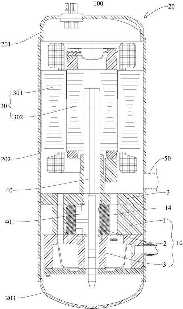
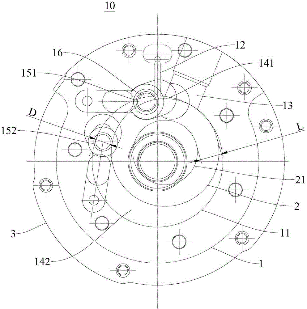
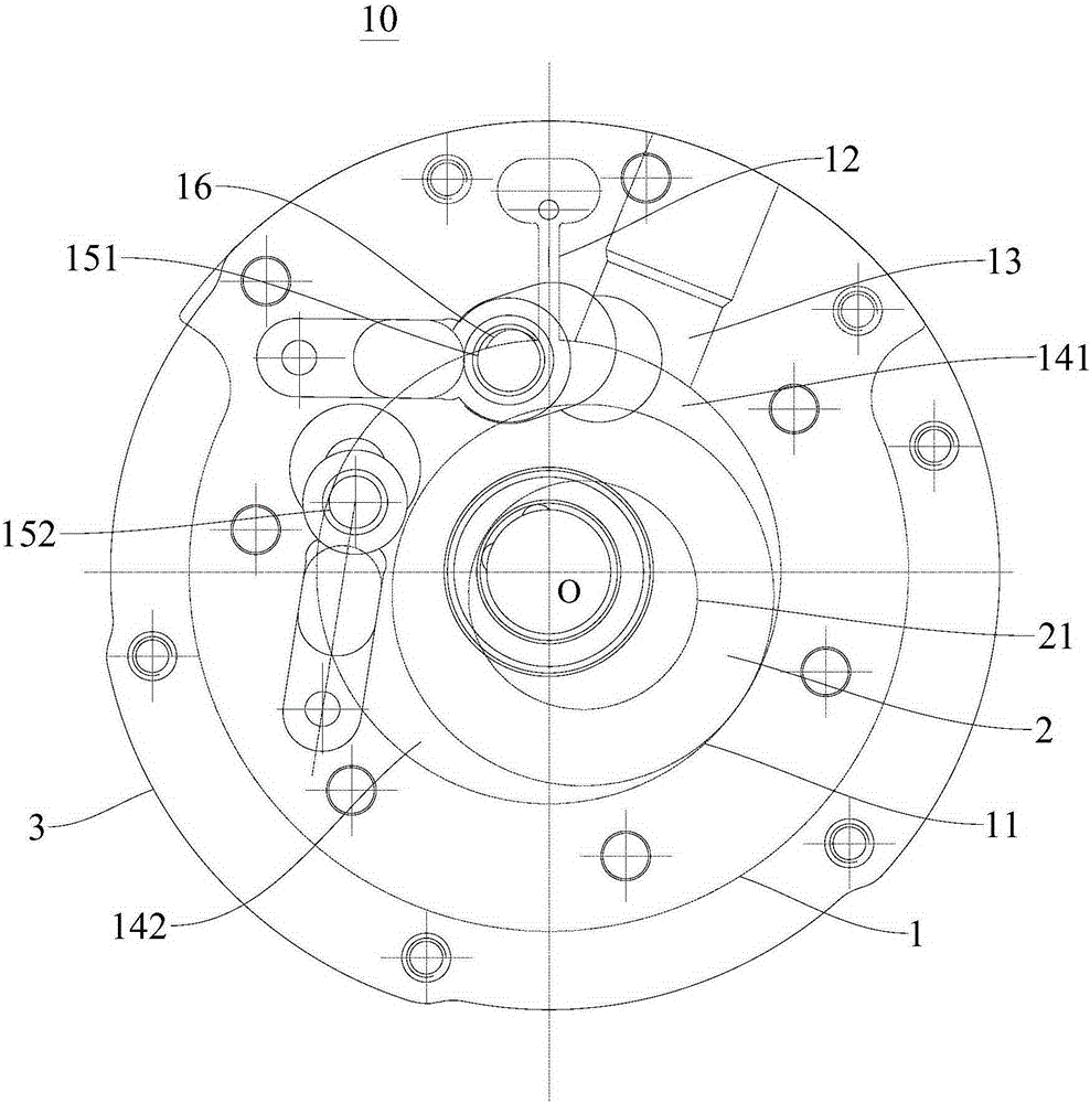
The invention discloses a rotary compressor and a compression mechanism thereof. The compression mechanism comprises an air cylinder, a piston and a bearing, wherein an air cylinder hole and a slide plate groove are formed in the air cylinder; the piston is arranged on an eccentric part of a crankshaft in a sleeving manner and is stored in the air cylinder hole in a way of eccentrically rotating surrounding the center of the air cylinder hole; the bearing is arranged on the upper end or the lower end of the air cylinder, an air cylinder cavity is collectively formed between the end surface of the bearing and the air cylinder hole, a plurality of exhaustion holes which are communicated with the air cylinder cavity are formed in the bearing, and the plurality of exhaustion holes are arranged at intervals along a rotating path of the piston. The compression mechanism is small in ventilation resistance, low in noise, small in exhaustion clearance volume, simple in structure and low in cost.

Description

technical field [0001] The invention relates to the field of compressors, in particular to a compression mechanism of a rotary compressor and a rotary compressor with the compression mechanism. Background technique [0002] Existing a lot of rotary compressors only exhaust on one side of the bearing through the oblique exhaust cut on the cylinder during the exhaust stage, so the exhaust resistance is large. [0003] In order to solve the above problems, the existing large-displacement compressors and compressors with a relatively high cylinder height adopt a structure in which the main and auxiliary bearings are exhausted separately. This structure can effectively reduce the exhaust resistance, but it also causes high exhaust noise. A series of shortcomings such as large exhaust clearance volume, deformation of the main and auxiliary bearing valve seats, large assembly clearance requirements, and large leakage on the piston end face, especially in the design process of the l...

Claims


Application Information

Patent Timeline
Patent Type & Authority Applications(China)
IPC IPC(8): F04C18/356F04C29/00F04C29/12
Inventor 黎法运高斌谢静
Owner GUANGDONG MEIZHI COMPRESSOR
Why Eureka
Try Eureka