Rotary type compressor capable of being turbocharged
A rotary compressor and turbocharging technology, which is applied in the field of compressors, can solve the problems of small flow area, large exhaust resistance, and exhaust resistance of the motor stator, and achieve light weight, increased exhaust pressure, and reduced exhaust. The effect of air resistance
- Summary
- Abstract
- Description
- Claims
- Application Information
AI Technical Summary
Problems solved by technology
Method used
Image
Examples
Embodiment 1
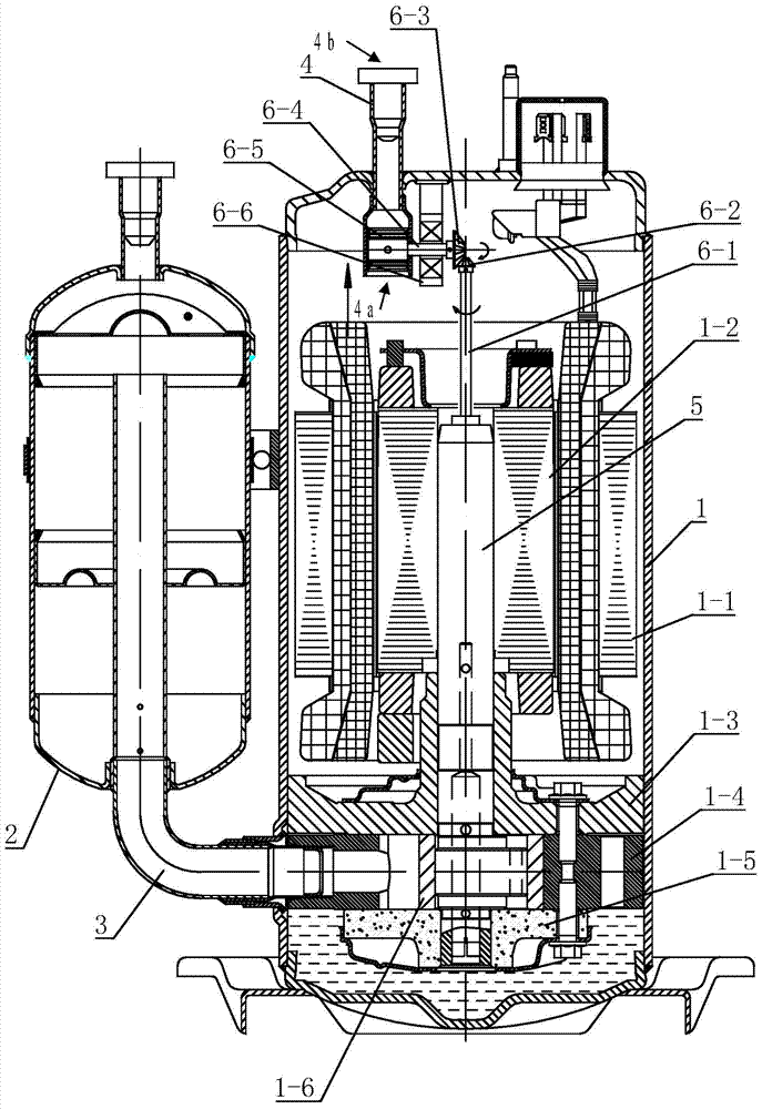
[0024] Such as figure 1 As shown, the compressor of this embodiment includes a closed casing 1, a motor assembly and a compression pump body assembly arranged inside the closed casing 1, a gas-liquid separator 2 arranged on one side of the closed casing 1, and the gas-liquid separator 2 communicates with the compression pump body of the compressor through the intake elbow 3, so that the refrigerant enters the cylinder of the compressor from the gas-liquid separator 2. Exhaust pipe 4 is arranged on the upper end of closed casing 1, and exhaust pipe 4 comprises inlet port 4a and gas outlet port 4b, and gas enters exhaust pipe 4 from inlet port 4a, discharges exhaust pipe 4 from outlet port 4b, by The compressed high-temperature and high-pressure gas enters the circulation system from the exhaust pipe 4.
[0025] The motor assembly of the utility model includes a stator 1-1 fixed on the upper inner wall of the closed casing 1, and a rotor 1-2 rotatably arranged in the stator 1-1...
Embodiment 2
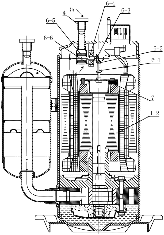
[0030] Such as figure 2 As shown, the difference between this embodiment and Embodiment 1 is that a mounting plate 7 is arranged at the top of the rotor 1-2, the first transmission rod 6-1 is riveted and fixed on the mounting plate 7, and when the rotor 1-2 rotates, it is fixed The first transmission rod 6-1 on the mounting plate 7 rotates synchronously with the rotor 1-2, and transmits the rotational kinetic energy of the rotor 1-2 through the first and second transmission gears and the second transmission rod that are engaged with each other. 4 is delivered to the turbine fan blade 6-5, and the turbine fan blade 6-5 rotates to draw air upwards, thereby improving the exhaust capacity of the compressor.
Embodiment 3
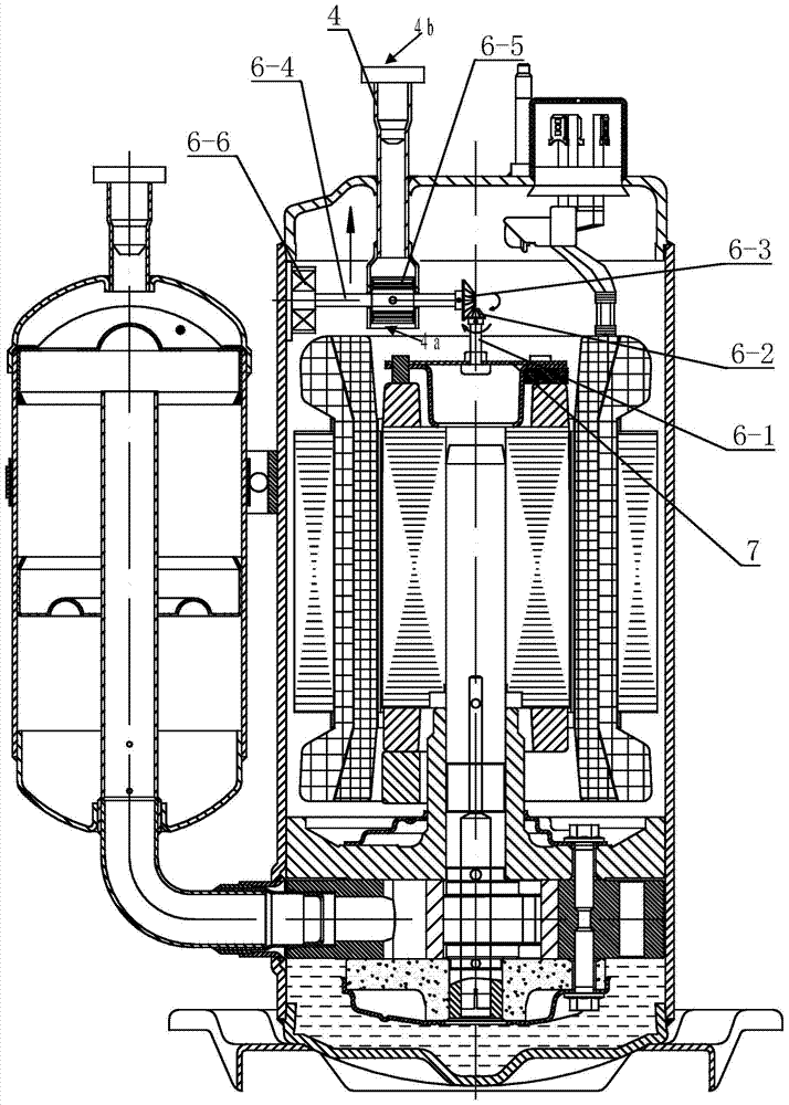
[0032] Such as image 3 As shown, the difference between this embodiment and Embodiment 2 is that the bearing assembly 6-6 of this embodiment is fixed on the side wall of the closed housing 1, and one end of the second transmission rod 6-4 is installed on the bearing assembly 6-6. 6, the second transmission rod 6-4 passes through the exhaust pipe 4, and the turbine blade 6-5 is arranged in the middle of the second transmission rod 6-5. The second transmission gear 6-3 arranged at the other end of the second transmission rod 6-5 meshes with the first transmission gear 6-2 arranged at the top of the first transmission rod 6-1 for transmission.
PUM
 Abstract
Description
Claims
Application Information
 - R&D
- Intellectual Property
- Life Sciences
- Materials
- Tech Scout
- Unparalleled Data Quality
- Higher Quality Content
- 60% Fewer Hallucinations
Browse by: Latest US Patents, China's latest patents, Technical Efficacy Thesaurus, Application Domain, Technology Topic, Popular Technical Reports.
© 2025 PatSnap. All rights reserved.Legal|Privacy policy|Modern Slavery Act Transparency Statement|Sitemap|About US| Contact US: help@patsnap.com


