New automatic welding equipment for exhaust manifold and working method of new automatic welding equipment

An exhaust manifold, automatic welding technology, applied in welding equipment, welding equipment, auxiliary welding equipment and other directions, can solve the problems of unstable welding quality, time-consuming and labor-intensive, affecting production efficiency, etc.

Inactive Publication Date: 2019-02-15
李春洪
View PDF0 Cites 2 Cited by
  • Summary
  • Abstract
  • Description
  • Claims
  • Application Information

AI Technical Summary

Problems solved by technology

[0002] Exhaust manifold is an important part in automobile manufacturing. At present, manual welding is mainly used in the welding process of exhaust manifold. However, the existing manual welding cannot complete the welding of the weld seam at one time, and the weld seam is uniform during welding. poor performance, resulting in unstable welding quality; at the same time, it is necessary to repeatedly fix the exhaust manifold in the fixture to adjust the butt weld during welding, which seriously affects production efficiency and increases labor c

Method used


Image

  • New automatic welding equipment for exhaust manifold and working method of new automatic welding equipment
  • New automatic welding equipment for exhaust manifold and working method of new automatic welding equipment
  • New automatic welding equipment for exhaust manifold and working method of new automatic welding equipment

Examples


Embodiment 1

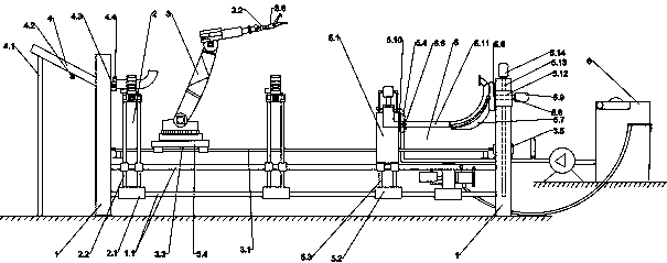
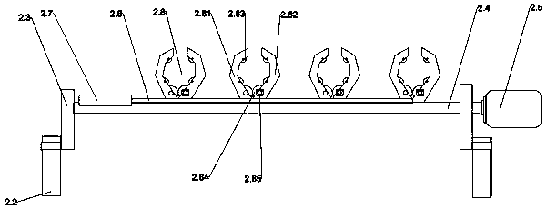
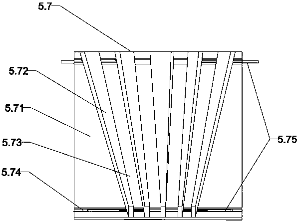
[0034] 1. A new type of automatic welding equipment for exhaust manifolds, including equipment rack 1, single-stage welding table 2, multi-functional manipulator 3, flange slideway 4, combined welding table 5 and polishing device 6; the The equipment rack 1 is provided with four groups, each of which is fixedly connected by two upper and lower horizontal slide bars 1.1, the single-stage welding table 2 is provided with two groups, and the bottom of the single-section welding table 2 is provided with a linear motor I2.1, the linear motor I2.1 is sleeved on the sliding rod 1.1, the top of the linear motor I2.1 is fixed with four support rods I2.2, and the top of the support rod I2.2 is fixed on two sets of On the bracket 2.3, the middle of the bracket 2.3 is provided with a rotating shaft 2.4, the rotating shaft 2.4 passes through the bracket 2.3, the end of the rotating shaft 2.4 is connected with a turning servo motor 2.5, and the rotating shaft 2.4 is slidably sleeved with a c...

Embodiment 2

[0042] The structure and principle of the second embodiment are basically the same as those of the first embodiment. The difference is that the middle and lower part of the flange slideway 4 is provided with a stop cylinder 4.2. The stop cylinder 4.2 can adjust the sliding pressure of the flange to avoid a large number of flanges. If the sliding pressure is too large, the clamping cylinder II cannot be fully clamped, causing the flange to fall off.

Embodiment 3

[0044] The structure and principle of the third embodiment are basically the same as those of the first embodiment, the difference is that the piston chamber I6.11 and the piston chamber II6.26 are provided with a pressure detection device 6.27, and the pressure detection device 6.27 can detect the grinding and extrusion. The pressure is fed back to the control system to control the polishing pressure inside the exhaust manifold to improve polishing quality.


PUM


Abstract

The invention provides new automatic welding equipment for an exhaust manifold and a working method of the new automatic welding equipment. The new automatic welding equipment comprises equipment racks, single-section welding worktables, a multifunctional manipulator, a flange slideway, a combined welding worktable and a polishing device; the single-section welding worktables can move butt weld leftwards and rightwards and overturn the butt weld, a weldment can be rotated through arranged clamping claws during welding, all sections of manifolds can be combined and butted together through the combined welding worktable, and after an exhaust main pipe is welded, polishing can be automatically conducted; and the multifunctional manipulator is provided with an automatic clamping structure, andworking heads can be automatically replaced and clamped through the automatic clamping mechanism. According to the new automatic welding equipment for the exhaust manifold and the working method of the new automatic welding equipment, segmented welding is conducted first, then overall welding is conducted, polishing is conducted after welding, the working heads of the equipment can be automatically replaced, thus the functions of welding, carrying, detecting and stress removing are achieved, and the new automatic welding equipment is quite suitable for welding of the exhaust manifold.

Description

technical field [0001] The invention belongs to the technical field of automobile parts processing, and relates to a new type of automatic welding equipment for exhaust manifolds and a working method thereof. Background technique [0002] Exhaust manifold is an important component in automobile manufacturing. At present, manual welding is mainly used in the welding process of exhaust manifold. However, the existing manual welding cannot complete the welding of the welding seam at one time, and the welding seam is uniform during welding. poor performance, resulting in unstable welding quality; at the same time, it is necessary to repeatedly fix the exhaust manifold in the fixture to adjust the butt weld, which will seriously affect the production efficiency and increase labor costs; and the inner surface of the exhaust manifold after welding is completed. The existence of welding slag, burrs and other debris in the weld will increase the exhaust resistance, and the exhaust wi...

Claims


Application Information

Patent Timeline
IPC IPC(8): B23K31/02B23K37/00B24B29/08B24B41/06
CPCB23K31/02B23K37/00B24B29/08B24B41/067
Inventor 李春洪
Owner 李春洪
Why Eureka
Try Eureka