Environment-friendly exhaust manifold automatic welding equipment and work method thereof

An exhaust manifold, automatic welding technology, applied in welding equipment, welding equipment, auxiliary welding equipment, etc., can solve problems such as affecting production efficiency, increasing exhaust resistance, and welding smoke affecting the working environment.

Inactive Publication Date: 2019-02-15
李春洪
View PDF0 Cites 5 Cited by
  • Summary
  • Abstract
  • Description
  • Claims
  • Application Information

AI Technical Summary

Problems solved by technology

[0002] Exhaust manifold is an important part in automobile manufacturing. At present, manual welding is mainly used in the welding process of exhaust manifold. However, the existing manual welding cannot complete the welding of the weld seam at one time, and the weld seam is uniform during welding. poor performance, resulting in unstable welding quality; at the same time, it is necessary to repeatedly fix the exhaust manifold in the fixture to adjust the butt weld during welding, which seriously affects production efficiency and increases labor cost

Method used


Image

  • Environment-friendly exhaust manifold automatic welding equipment and work method thereof
  • Environment-friendly exhaust manifold automatic welding equipment and work method thereof
  • Environment-friendly exhaust manifold automatic welding equipment and work method thereof

Examples


Embodiment 1

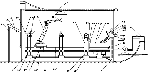
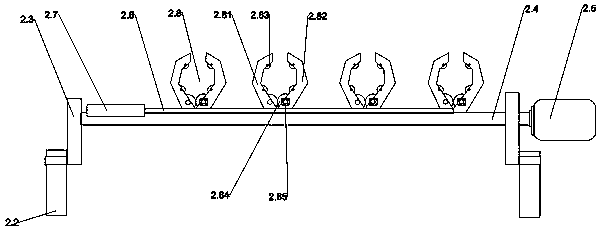
[0034] 1. An environment-friendly exhaust manifold automatic welding equipment, comprising an equipment frame 1, a single-section welding workbench 2, a welding handling detection manipulator 3, a flange slideway 4, a combined welding workbench 5 and a polishing device 6; The equipment rack 1 is provided with four groups, each group is fixedly connected by two upper and lower horizontal slide bars 1.1, the single-section welding workbench 2 is provided with two groups, and the bottom of the single-section welding workbench 2 is provided with a straight line The motor I2.1, the linear motor I2.1 is sleeved on the slide rod 1.1, the top of the linear motor I2.1 is fixed with four support rods I2.2, and the top of the support rod I2.2 is fixed on two On the bracket 2.3, the middle part of the bracket 2.3 is provided with a rotating shaft 2.4, the rotating shaft 2.4 passes through the bracket 2.3, the end of the rotating shaft 2.4 is connected with a turning servo motor 2.5, and th...

Embodiment 2

[0041] The structure and principle of this embodiment 2 are basically the same as that of embodiment 1, the difference is that the middle and lower part of the flange slideway 4 is provided with a stop cylinder 4.2, and the stop cylinder 4.2 can adjust the sliding pressure of the flange to avoid a large number of flanges If the sliding pressure is too large, the clamping cylinder II cannot be fully clamped, causing the flange to drop.

Embodiment 3

[0043] The structure and principle of this embodiment 3 are basically the same as that of embodiment 1, the difference is that the piston chamber I 6.11 and the piston chamber II 6.26 are equipped with a pressure detection device 6.27, and the pressure detection device 6.27 can detect the grinding and extrusion The pressure is fed back to the control system to control the polishing pressure inside the exhaust manifold to improve the polishing quality.


PUM


Abstract

The invention provides environment-friendly exhaust manifold automatic welding equipment and a work method thereof. The automatic welding equipment comprises an equipment rack, single-segment weldingworktables, a welding carrying detection mechanical arm, a flange sliding way, a combined welding worktable, a polishing device and a welding fume treatment device; the single-segment welding worktables can move and turn over abut-joint welding lines left and right, a clamping jaw can rotate a welding part during welding, a clamping welding device of the welding carrying detection mechanical arm has welding, carrying and detection functions, the combined welding worktable enables all segments of manifolds to be combined and in abut joint, after an exhaust main pipe is welded, the polishing program can be automatically started, and the welding fume treatment device is arranged on the top of the equipment, and can be automatically moved to the position above the welding part to extract welding fume. The welding treatment device is arranged, the welding fume generated by welding can be automatically collected and treated and then exhausted, harmful gas in a welding workshop can be effectively reduced, and the equipment can quite meet the modern environment-friendly production needs.

Description

technical field [0001] The invention belongs to the technical field of auto parts processing, and relates to an environment-friendly exhaust manifold automatic welding device and a working method thereof. Background technique [0002] Exhaust manifold is an important part in automobile manufacturing. At present, manual welding is mainly used in the welding process of exhaust manifold. However, the existing manual welding cannot complete the welding of the weld seam at one time, and the weld seam is uniform during welding. poor performance, resulting in unstable welding quality; at the same time, it is necessary to repeatedly fix the exhaust manifold in the fixture to adjust the butt weld during welding, which seriously affects production efficiency and increases labor costs; and the inner surface of the exhaust manifold after welding is completed There are welding slag, burrs and other debris in the weld, which will increase the exhaust resistance, and the exhaust will be di...

Claims


Application Information

Patent Timeline
IPC IPC(8): B23K31/02B23K37/00B24C3/32
CPCB23K31/02B23K37/00B24C3/325
Inventor 李春洪
Owner 李春洪
Why Eureka
Try Eureka