Upper flange of compressor and compressor comprising upper flange

A compressor and upper flange technology, applied in the field of compressors, can solve problems such as increased clearance volume, large exhaust resistance, and increased power consumption, and achieve the effects of reducing exhaust resistance, avoiding overcompression, and improving energy efficiency

Inactive Publication Date: 2016-09-07
ZHUHAI LANDA COMPRESSOR +1
View PDF10 Cites 6 Cited by
  • Summary
  • Abstract
  • Description
  • Claims
  • Application Information

AI Technical Summary

Problems solved by technology

Whether it is single exhaust or double exhaust, the exhaust port is usually set at the end of the compression stroke (the end position of the exhaust cavity of the compression cavity). When the gas reaches the exhaust pressure, the compressor needs to release the high pressure There are problems of overcompression and large exhaust resistance when the gas is compressed for a certain stroke; in addition, for the dual exhaust scheme, two oblique cuts need to be made on the edge of the cylinder, which increases the harmful clearance volume and leads to increased power consumption

Method used


Image

  • Upper flange of compressor and compressor comprising upper flange
  • Upper flange of compressor and compressor comprising upper flange
  • Upper flange of compressor and compressor comprising upper flange

Examples


Embodiment 1

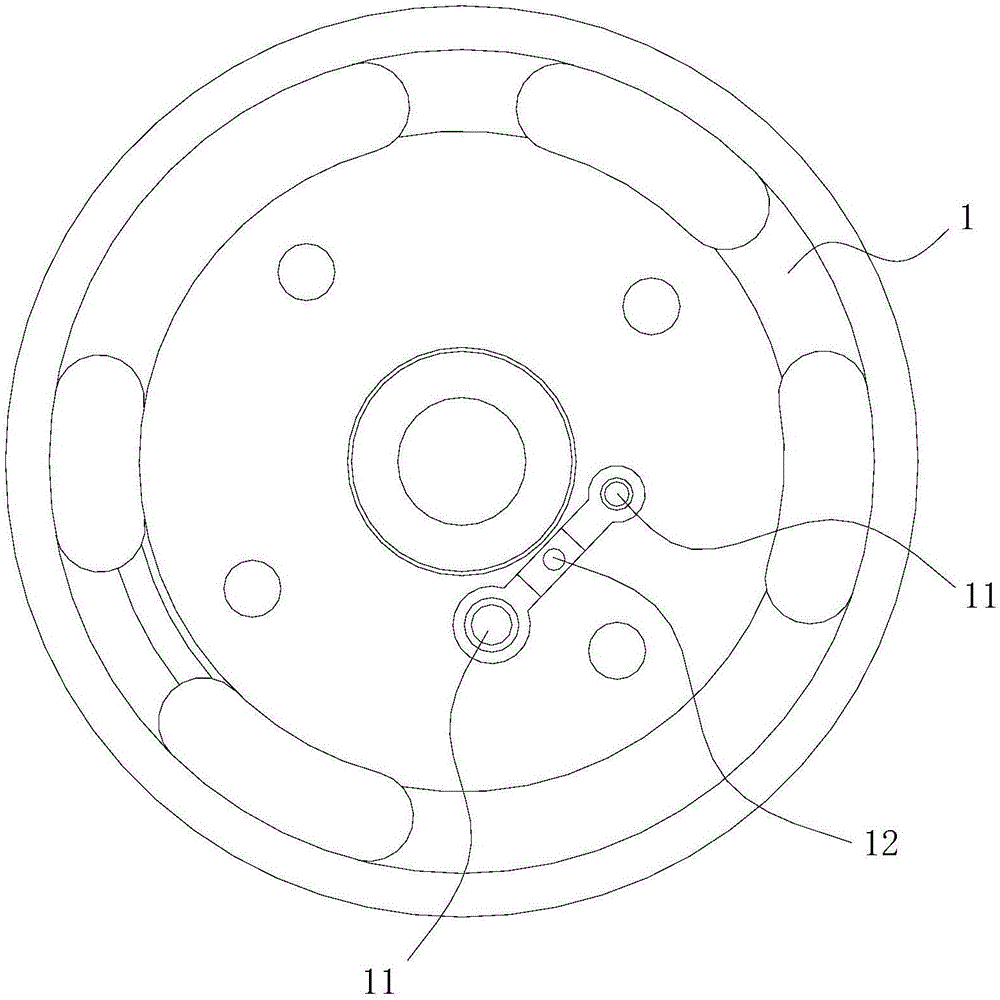
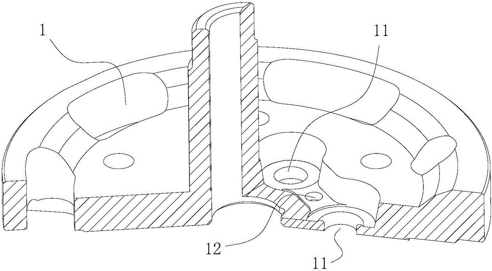
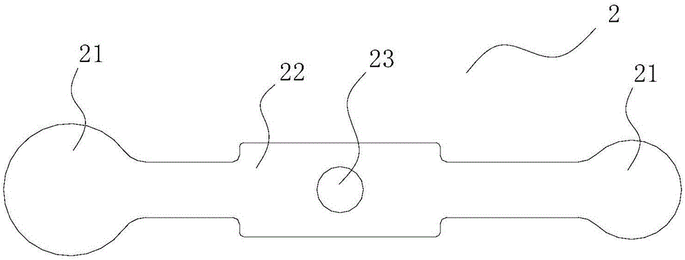
[0034] This preferred embodiment discloses an upper flange of a compressor. Such as figure 1 and figure 2 As shown, the upper flange includes a valve body 1, and two exhaust ports 11 are opened on the valve body 1, wherein one exhaust port 11 is located at the termination position of the exhaust chamber of the compression chamber, and the other exhaust port 11 is located at The initial position of the exhaust chamber of the compression chamber, or between the initial position and the end position; the two exhaust ports 11 are covered with a valve plate 2, and the valve plate 2 is installed on the valve body 1 through the valve plate baffle 3 . Wherein, the areas of the two exhaust ports 11 may be different.

[0035] An exhaust port 11 is added on the basis of an exhaust port 11 structure on the existing upper flange, and the newly added exhaust port 11 is located in front of the original exhaust port 11 (the original exhaust port Port 11 is located at the end position of ...

Embodiment 2

[0040] This preferred embodiment discloses an upper flange of a compressor, the structure of which is basically the same as that of the preferred embodiment 1, the difference is that, as Figure 6 As shown, the valve plate 2 includes two independent valve plate bodies 20 , one end of each valve plate body 20 forms a covered end 21 , and the other end forms a fixed end 25 , and the fixed end 25 is provided with a valve plate mounting hole 23 . The two valve plate bodies 20 are arranged in a figure-eight shape, the two covering ends 21 are located on the inside, and the two valve plate mounting holes 23 are located on the outside.

[0041] The independent valve body 20 can be the valve body used for the upper flange of the existing compressor, and there is no need to prepare a new valve body 20, which reduces the manufacturing cost.

Embodiment 3

[0043] This preferred embodiment discloses an upper flange of a compressor, the structure of which is basically the same as that of the preferred embodiment 2, the difference is that, as Figure 7 As shown, two valve plate bodies 20 are arranged in parallel. During the exhaust process, the force on the two valve body 20 is the same, and the exhaust is uniform.


PUM


Abstract

The invention discloses an upper flange of a compressor and the compressor comprising the upper flange and belongs to the technical field of compressors. The upper flange of the compressor and the compressor comprising the upper flange are designed to solve the problem that the exhaust resistance of an existing device is large. The upper flange of the compressor comprises a valve body. Two exhaust ports are formed in the valve body. One exhaust port is located in the stop position of an exhaust cavity of a compressing cavity, and the other exhaust port is located in the initial position of the exhaust cavity of the compressing cavity, or located between the initial position and the stop position. The two exhaust ports are covered with a valve block. The valve block is installed on the valve body through a valve block baffle. The compressor comprises an air cylinder and a lower flange and further comprises the upper flange of the compressor. By the adoption of the upper flange of the compressor and the compressor comprising the upper flange, compressed gas can be exhausted in advance, the exhaust resistance is reduced, over-compression of refrigerants is avoided, the power consumption of the compressor is reduced, and the energy efficiency is improved.

Description

technical field [0001] The invention relates to the technical field of compressors, in particular to an upper flange of a compressor and a compressor including the upper flange. Background technique [0002] In the compressor, the cylinder and the upper and lower flanges respectively arranged at the upper and lower ends of the cylinder are important components for refrigerant compression. [0003] Existing rotary compressors are generally single exhaust (upper exhaust) or double exhaust (upper exhaust, lower exhaust). Whether it is single exhaust or double exhaust, the exhaust port is usually set at the end of the compression stroke (the end position of the exhaust cavity of the compression cavity). When the gas reaches the exhaust pressure, the compressor needs to release the high pressure If the gas is compressed for a certain stroke, there are problems of overcompression and large exhaust resistance; in addition, for the dual exhaust scheme, two oblique cuts need to be m...

Claims


Application Information

Patent Timeline
Patent Type & Authority Applications(China)
IPC IPC(8): F04C29/00F04C29/12
CPCF04C29/00F04C29/12
Inventor 余少波范少稳林婵琼
Owner ZHUHAI LANDA COMPRESSOR
Why Eureka
Try Eureka