A Design Method of Coiled Tubing

A design method, oil pipe technology, applied in computing, instrumentation, electrical digital data processing, etc., can solve the problems of increased computing costs and poor results, and achieve the effect of reducing the working process

Active Publication Date: 2019-06-18
SHANDONG KERUI MACHINERY MFG
View PDF6 Cites 0 Cited by
  • Summary
  • Abstract
  • Description
  • Claims
  • Application Information

AI Technical Summary

Problems solved by technology

Through decades of accumulated experience, there are some empirical calculation formulas for drum capacity calculation, variable-wall-thickness coiled tubing design, and load distribution calculation. However, these calculation methods have not become a system, and they are all judged by experience and on-site construction environment. , so that the calculation cost increases and the effect is not good

Method used


Image

  • A Design Method of Coiled Tubing
  • A Design Method of Coiled Tubing
  • A Design Method of Coiled Tubing

Examples


Embodiment 1

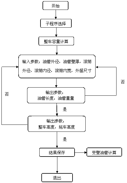
[0038] Tubing length and tubing weight calculation:

[0039] In the H-I mathematical model, set oil pipe diameter A, drum outer diameter B, drum inner diameter C, drum inner width D, flange height E, oil pipe turns F, oil pipe layers G, oil pipe length H, oil pipe weight I, and oil pipe density J , tubing wall thickness K, where:

[0040] E=(B-C) / 2, F=int(D / A), G=int[(B-C) / 2×A];

[0041]

[0042] Depend on figure 1 , if the calculation result obtained after calculation is that the size of the tubing drum cannot meet the requirements of the tubing length desired by the user, then adjust the outer diameter and inner width of the tubing drum until the requirements can be met.

[0043] The calculation results are often non-round sizes. For example, it is expected that the tubing drum can accommodate 1.5” tubing 5 with a length of 5000m, but the actual calculated result is 5150m and the weight of the tubing with a length of 5150m. You can set the expected tubing length and the...

Embodiment 2

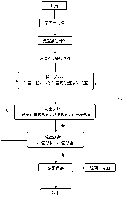
[0046] Tubing tensile load, yield load and bearing load calculation:

[0047] In the Q-P model, the tensile strength L of the tubing, the yield strength M, the tensile load O, the yield load P, and the withstand load Q are set, where:

[0048] O={[A×A-(A-2K)×(A-2K)] / 4}×3.14×L;

[0049] P={[A×A-(A-2K)×(A-2K)] / 4}×3.14×P

[0050] Q=P-∑I

[0051] Where ∑I is the sum of the tubing weights.

[0052] The variable-wall tubing calculation can realize the selection of the tubing strength grade, input the outer diameter of the tubing, and input the length and wall thickness of the segmented tubing. The calculation program can automatically calculate the weight of each section of tubing, the maximum tensile load, the maximum yield load and the section of tubing able to withstand the load.

[0053] The number of variable-wall-thickness tubing sections that can be calculated by this method is up to 5 sections.

[0054] It can be determined whether the design of variable-wall-thickness ...

Embodiment 3

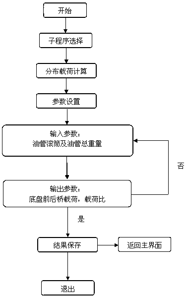
[0057] Vehicle height calculation and distributed load calculation:

[0058] u 0 -U 1 In the mathematical model, the load on the front axle is T, the load on the rear axle is U, and the weight of the body is G 0 , the distance L between the bodywork and the front axle 1 , the distance L between the bodywork and the rear axle 2 , the distance L between the front and rear axles 0 , then G 0 Loads on the rear axle and G 0 The loads on the front axle are:

[0059] f 0 =G 0 × L 1 / L 0 , F 1 =G 0 × L 2 / L 0

[0060] Then the total load on the rear axle is U 0 =∑F 0 , the total load U on the front axle 1 =∑F 1 ;

[0061] Then the load ratio of the front axle to the rear axle is:

[0062]

[0063] Depend on image 3 , The distributed load calculation can realize the setting of the allowable load of the front and rear axles. After inputting the weight of the tubing drum and tubing, the calculation program automatically calculates and outputs the relationship be...


PUM


Abstract

The invention relates to the field of petroleum equipment, and in particular relates to a design method of a continuous oil pipe. The design method comprises the following steps: calculating the pipe volume, the weight of an oil pipe, the height of a whole vehicle, the load distribution of the whole vehicle, the variable-wall-thickness pipe diameter allowable load and the lifting force of an injection head, which are relevant to a specific outer diameter, of an oil pipe rotary drum by inputting required parameters, wherein four calculation processes of whole vehicle volume calculation, variable-wall oil pipe calculation, load distribution calculation and injection head calculation are included. According to the design method of the continuous oil pipe, the problems that the calculation process of a continuous oil pipe designer is complicated, and the continuous oil pipe designer consults information of relevant components difficultly are solved; the pipe volume, the weight of the oil pipe, the height of the whole vehicle, the load distribution of the whole vehicle, the variable-wall-thickness pipe diameter allowable load and the lifting force of the injection head, which are relevant to the specific outer diameter, of the oil pipe rotary drum can be automatically calculated by inputting the necessary parameters; and therefore, the complexity of the working process of the designer is alleviated.

Description

technical field [0001] The invention relates to the field of petroleum equipment, in particular to a method for designing a coiled tubing. Background technique [0002] Since the invention of coiled tubing equipment in the 1960s, the design, manufacture and operation technology of the equipment have gradually matured. Through decades of accumulated experience, there are some empirical calculation formulas for drum capacity calculation, variable-wall-thickness coiled tubing design, and load distribution calculation. However, these calculation methods have not become a system, and they are all judged by experience and on-site construction environment. , so that the calculation cost increases and the effect is not good. Contents of the invention [0003] In order to solve the above technical problems, the present invention provides a method that can be used for the calculation of the capacity of the tubing drum, the calculation of the weight of the tubing, the design of the ...

Claims


Application Information

Patent Timeline
Patent Type & Authority Patents(China)
IPC IPC(8): G06F17/50
Inventor 张兴荣姚占伟潘海成
Owner SHANDONG KERUI MACHINERY MFG
Why Eureka
Try Eureka