Sucker rod high-pressure jet flow mechanical rotary brush composite scale removing device and method

A high-pressure jet and sucker rod technology is applied in the fields of oil field cleaning, high-pressure jet, fracture mechanics, and hydraulic motors. It can solve the problems of shortening the pump inspection cycle, heavy workload, and high cost, and achieves reduced complex work, strong in-depth capabilities, and The effect of high torque

Active Publication Date: 2020-11-27
DAQING UNIVERSITIES GASOLINEEUM TECH
View PDF5 Cites 0 Cited by
  • Summary
  • Abstract
  • Description
  • Claims
  • Application Information

AI Technical Summary

Problems solved by technology

Due to the high viscosity of the polymer, the easy scaling of alkali, and the large amount of sand flowing into the wellbore caused by high-pressure oil displacement, the rods, pipes, and pumps of the oil well are massively fouled and blocked, reducing the pump inspection cycle and increasing the workload. The frequency of replacement has also increased significantly, and the maintenance cost has risen sharply
At present, the common measures after rod tube pump fouling and blockage: stop the well operation, take out the rod tube pump and transport it back to the maintenance workshop of the base, clean, descale and repair it. The cycle is long and the cost is high; the chemical immersion cleaning method occupies a large space, the immersion cycle is long, and the pollution discharge is large; while the high-pressure jet method has made great progress, but requires a high high-pressure water jet pressure, which affects the performance and quality of high-pressure equipment High requirements, high equipment cost, high operation and maintenance costs

Method used


Image

  • Sucker rod high-pressure jet flow mechanical rotary brush composite scale removing device and method
  • Sucker rod high-pressure jet flow mechanical rotary brush composite scale removing device and method

Examples


Embodiment 1

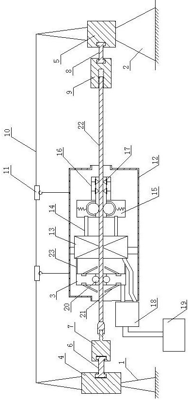
[0020] A high-pressure jet mechanical rotary brush composite descaling device for sucker rods of the present invention includes a front support frame 1, a rear support frame 2 and a cleaning nozzle 3, and the front support frame 1 is equipped with a front fixing frame 4 and a rear support frame 2 The rear fixing frame 5 is installed on the top, and the inner side of the front fixing frame 4 is flexibly connected with the fixed and tensioned male joint 7 of the rod end through the front tightening connection short rod 6, and the inner side of the rear fixing frame 5 is fixed with the rod end through the rear tightening connection short rod 8 Tighten the flexible connection of the female joint 9, the upper part between the front fixed frame 4 and the rear fixed frame 5 is fixed with a slideway beam 10, the slideway beam 10 is equipped with a slider 11, and a circular protective sleeve 12 is hoisted below the slider 11, A hydraulic motor 13 is fixedly installed in the circular pro...

Embodiment 2

[0022] A sucker rod high-pressure jet mechanical rotary brush composite descaling device of the present invention includes a front support frame 1, a rear support frame 2 and a cleaning nozzle 3, and the front support frame 1 is equipped with a front fixing frame 4 and a rear support frame 2. The rear fixed frame 5 is installed, and the inner side of the front fixed frame 4 is flexibly connected with the fixed and tensioned male joint 7 of the rod end through the front tension connection short rod 6, and the rear fixed frame 5 is connected with the fixed tension rod 8 and the rod end by the rear tensioned connection short rod 8. The tight female joint 9 is movably connected, and the upper part between the front fixed frame 4 and the rear fixed frame 5 is fixed with a slideway crossbeam 10, the slideway crossbeam 10 is equipped with a slide block 11, and a circular protective sleeve 12 is hoisted below the slide block 11. The hydraulic motor 13 is fixedly installed in the protec...

Embodiment 3

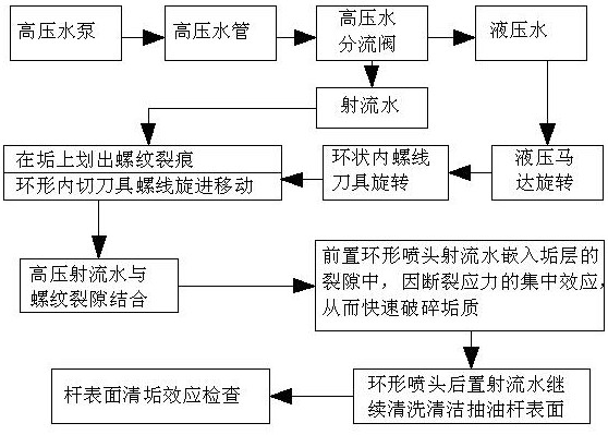
[0025] A kind of sucker rod high-pressure jet mechanical rotary brush composite descaling method of the present invention, through the following steps:

[0026] a. Pass the sucker rod to be cleaned through the cleaning nozzle and the center hole of the hydraulic motor, and fix both ends on the rod end fixed tension male joint and the rod end fixed tension female joint;

[0027] b. Start the high-pressure water pump, the high-pressure water flows into the diverter valve through the high-pressure water pipe, part of the high-speed fluid enters the cleaning nozzle, and the other part of the high-pressure fluid enters the hydraulic motor to make it rotate;

[0028] c. The hydraulic motor drives the internal thread cutter to rotate;

[0029] d. The rotating internal thread cutter scratches the surface of the hard scale; the screw thread advance force drags the motor system to move forward;

[0030] e. The nozzle of the high-pressure nozzle ejects high-pressure jet water at high sp...


PUM


Abstract

The invention relates to a sucker rod high-pressure jet flow mechanical rotary brush composite scale removing device and method, and belongs to the field of oil field cleaning. The sucker rod high-pressure jet flow mechanical rotary brush composite scale removing device comprises a front supporting frame, a rear supporting frame and a cleaning spray head, a front fixing frame is installed on the front supporting frame, a rear fixing frame is installed on the rear supporting frame, the inner side of the front fixing frame is movably connected with a rod end fixing and tensioning male connectorthrough a front tensioning connecting short rod, the inner side of the rear fixing frame is movably connected with a rod end fixing and tensioning female connector through a rear tensioning connectingshort rod, a sliding way beam is fixed to the upper portion between the front fixing frame and the rear fixing frame, a hydraulic motor is fixedly installed in the circular protection sleeve, and a cleaning nozzle is fixedly mounted at the front part of the hydraulic motor. According to the sucker rod high-pressure jet flow mechanical rotary brush composite scale removing device and method, the mechanical scale removing advantage and the jet flow scale removing advantage are organically combined, the torque is large during mechanical scratching, cracks are likely to be generated, the rupturestress concentration effect is formed, the high-pressure jet flow is high in deepening capacity, the reverse crushing effect from inside to outside is generated, the speed is high, and the efficiencyis high.

Description

technical field [0001] The invention belongs to oilfield cleaning, high-pressure jet, hydraulic motor, fracture mechanics, etc., and in particular relates to a high-pressure jet mechanical rotary brush composite cleaning device and method for sucker rods. Background technique [0002] In order to improve the recovery of oil layers in the late stage of mature oilfields, after primary oil recovery with natural energy and secondary oil recovery with water injection, tertiary oil recovery is mostly used to inject polymers, alkalis and surfactants into the oil layers to improve oil displacement efficiency. Due to the high viscosity of the polymer, the easy scaling of alkali, and the large amount of sand flowing into the wellbore caused by high-pressure oil displacement, the rods, pipes, and pumps of the oil well are massively fouled and blocked, reducing the pump inspection cycle and increasing the workload. The frequency of replacement has also increased substantially, and maint...

Claims


Application Information

Patent Timeline
Patent Type & Authority Applications(China)
IPC IPC(8): B08B3/02B08B1/04B08B1/00B08B13/00
CPCB08B3/02B08B1/04B08B1/005B08B13/00
Inventor 李福军曹广胜王宏伟
Owner DAQING UNIVERSITIES GASOLINEEUM TECH
Why Eureka
Try Eureka