Shield machine rotary joint

A technology of rotary joints and shield machines, which is applied in mining equipment, earthwork drilling, tunnels, etc. It can solve the problems of small cutter head diameter and inability to install rotary joints, etc., and achieves the effect of good integrity and small space occupation

Active Publication Date: 2018-06-29
CHINA RAILWAY ENGINEERING EQUIPMENT GROUP CO LTD
View PDF8 Cites 0 Cited by
  • Summary
  • Abstract
  • Description
  • Claims
  • Application Information

AI Technical Summary

Problems solved by technology

[0005] The purpose of the present invention is to provide a shield machine rotary joint to solve the technical problem that the rotary joint cannot be installed due to the small diameter of the small shield machine cutterhead due to the above-mentioned shortcomings of the prior art.

Method used


Image

  • Shield machine rotary joint
  • Shield machine rotary joint
  • Shield machine rotary joint

Examples


Embodiment Construction

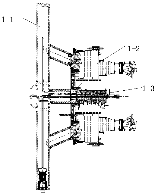
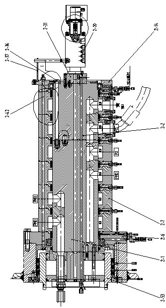
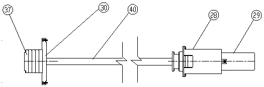
[0024] like Figure 2-7 As shown, the rotary joint of the shield machine of the present invention includes a small rotary joint 29, a rotor, a stator, a sealing assembly and a rotary support, the stator is sleeved outside the input end of the rotor, and the sealing assembly and the rotary support are arranged between the stator and the rotor. The small swivel joint 29 is connected with the input end of the rotor. The medium is injected into the rotor from the small rotary joint 29, and the output end of the rotor is connected with the cutter head, and the medium is injected into the front of the cutter head. When the medium is conveyed, the stator is fixed, and the rotor rotates synchronously with the cutter head.

[0025] The stator includes a shell 28, a connecting seat 9, a retaining ring 14 and a bolt one 15, the connecting seat 9 is fixed on the front part of the shell 28 by a bolt one 15, and the retaining ring 14 is fixed on the connecting seat 9 front part by a bolt on...


PUM


Abstract

The invention discloses a shield machine rotary joint, comprising a small rotary joint (29), a rotor, a stator, a sealing assembly and a rotary support, the stator is sleeved outside the input end of the rotor, and the sealing assembly and the rotary support are arranged between the stator and the rotor Between, the small rotary joint (29) is connected with the input end of the rotor, the stator includes the shell (28), the connection seat (9), the retaining ring (14) and the bolt one (15), the connection seat (9) passes through Bolt one (15) is fixed on the front portion of the casing (28), and the retaining ring (14) is fixed on the front portion of the connecting seat (9) by bolt one (15). The rotary joint of the shield machine of the invention has good integrity, takes up little space, and can inject medium in layers, and solves the technical problem that the rotary joint cannot be installed due to the small diameter of the cutter head of the small shield machine and the limited central driving space.

Description

technical field [0001] The invention belongs to the field of tunnel construction and excavation equipment shield machines, in particular to a shield machine rotary joint. Background technique [0002] With the continuous development of society, especially the continuous improvement of the degree of mechanization, the shield machine, as an important equipment in the machinery industry, has emerged with the rapid development of underground engineering and tunnel construction. [0003] like figure 1 As shown, the front end of a general earth pressure balance shield machine is composed of a cutter head 1-1, a driving device 1-2 and a rotary joint 1-3. The diameter of the cutter head 1-1 is generally more than six meters, and the driving device 1-2 are arranged on the right end face of the cutter head 1 and are evenly distributed around the circumference, and there is enough space in the middle of the cutter head 1-1 for installing the rotary joint. like figure 2 As shown in ...

Claims


Application Information

Patent Timeline
Patent Type & Authority Patents(China)
IPC IPC(8): E21D9/06
Inventor 谭顺辉胡燕伟郑康泰程永龙常巍峰
Owner CHINA RAILWAY ENGINEERING EQUIPMENT GROUP CO LTD
Why Eureka
Try Eureka