A wear-resistant cutting ring

A wear-resistant ring and cutting ring technology, which is applied to liquid variable volume machinery, components of pumping devices for elastic fluids, variable volume pump components, etc., can solve the problem of increased grinding volume, high cost, and cracking. and other problems, to achieve the effect of high impact resistance, improved service life and low production cost

Active Publication Date: 2018-02-09
泾县凡泽科技服务有限公司
View PDF9 Cites 0 Cited by
  • Summary
  • Abstract
  • Description
  • Claims
  • Application Information

AI Technical Summary

Problems solved by technology

[0003] The wear-resistant rings commonly used in the prior art mostly adopt integral and single-ring splicing structures. Regarding the integral structure wear-resistant ring, it does have good sealing performance, but the integrated pressing and sintering process is complicated. In order to ensure the machining accuracy, when sintering The remaining machining allowance will inevitably increase the amount of subsequent grinding
In addition, during the cooling process of components after high-temperature forming, there will be accumulation of internal stress. The larger the size of the component, the greater the accumulated internal stress. prone to cracking
Regarding the wear-resistant ring with a single-ring splicing structure, the splicing units that make up the wear-resistant ring include fan-shaped wear-resistant units. The fan-shaped wear-resistant units are easy to manufacture, but the joints of two adjacent wear-resistant units are easy to be worn and produce small cracks. Small cracks increase in depth and continue to expand radially along the cutting ring until they completely split the joint of the wear-resistant unit, resulting in poor sealing and affecting the service life of the cutting ring
In order to solve the problems in the above-mentioned solutions, an improved solution has been proposed in the prior art. The wear-resistant unit adopts a T-shaped or Z-shaped instead of a fan-shaped ring. Although the T-shaped or Z-shaped wear-resistant unit can solve the sealing problem, the The processing technology is complicated and the cost is high
[0004] Therefore, there is a technical problem that it is difficult to unify high wear resistance, ease of processing, and low cost in the wear-resistant ring in the prior art

Method used


Image

  • A wear-resistant cutting ring
  • A wear-resistant cutting ring
  • A wear-resistant cutting ring

Examples


Embodiment 1

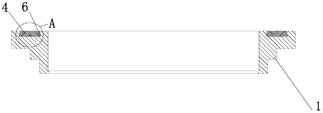
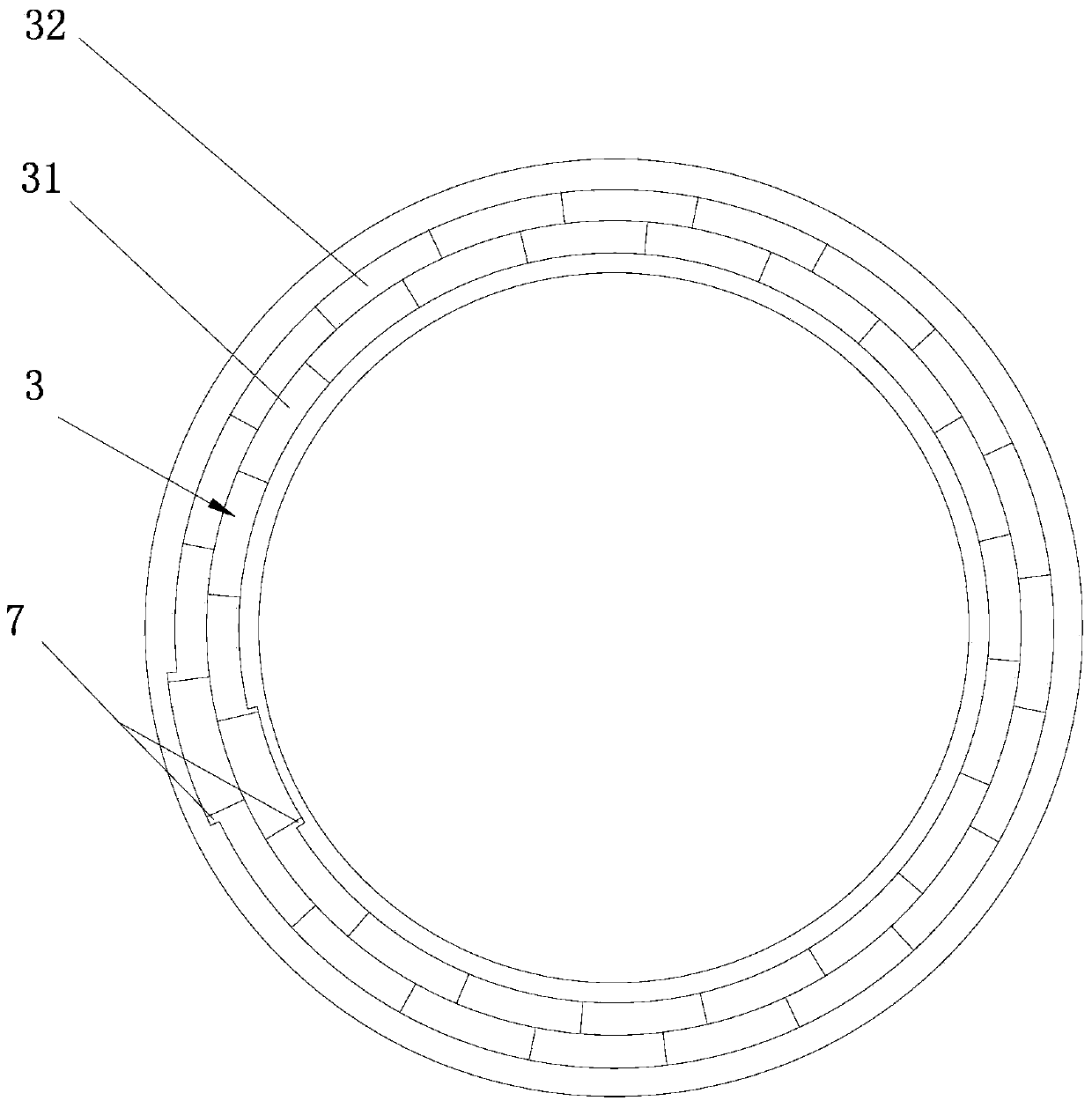
[0025] See attached figure 1 , 2 and 5, a wear-resistant cutting ring of the present invention, comprising a ring-shaped steel base 1 and a wear-resistant ring 3 embedded in the ring-shaped steel base 1 . In order to prevent leakage and ensure the sealing performance of the cutting ring, the working end surface of the annular steel base 1 is flush with the working end surface of the wear-resistant ring 3. The wear-resistant ring 3 is spliced ​​by several fan-shaped wear-resistant units 4, and the The cross-section of the unit 4 is dovetail-shaped, and the working end surface of the annular steel substrate 1 is provided with an annular dovetail groove 6 matched with the wear-resistant ring 3, and the annular dovetail groove 6 is provided with a gap for accommodating a single wear-resistant unit 4 7. There are several groups of wear-resistant rings 3, and several groups of wear-resistant rings 3 are arranged concentrically. In this embodiment, there are two groups of wear-resis...

Embodiment 2

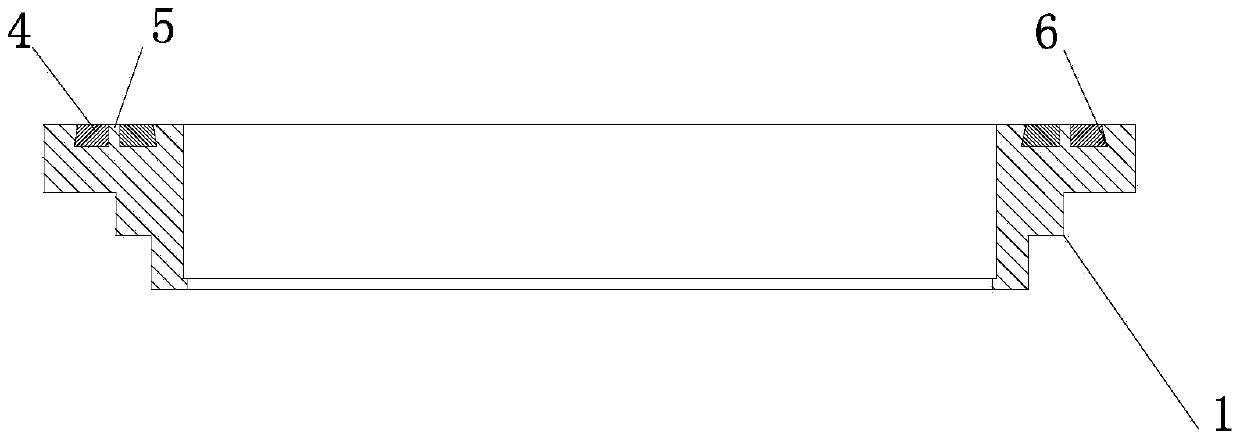
[0029] See attached image 3 And attached Figure 4 , the difference between this embodiment and Embodiment 1 is that an isolating ring 5 is arranged between the inner ring 31 and the outer ring 32, and the isolating ring 5 can well promote the solid connection between the wear-resistant unit 4 and the annular dovetail groove 6, and at the same time, it is more Effectively prevent the communication and expansion of cracks on the joints of the inner ring 31 and the outer ring 32 . Refer to Embodiment 1 for the rest of this embodiment.

Embodiment 3

[0031] See attached Figure 6 And attached Figure 7 The wear-resistant ring 3 is a group. Due to the special structure of the annular dovetail groove 6, a tight and firm fit is formed between the wear-resistant unit 4 and the annular dovetail groove 6, and the joint of the wear-resistant unit 4 is not easy to form cracks. Refer to Embodiment 1 for the rest of this embodiment.


PUM


Abstract

The invention discloses a wear-resistant cutting ring, which comprises a ring-shaped steel matrix and a wear-resistant ring embedded in the ring-shaped steel matrix. The working end surface of the steel matrix is ​​flush with the working end surface of the wear-resistant ring. The wear-resistant ring is spliced ​​by several fan-shaped annular wear-resistant units. The cross-section of the wear-resistant unit is dovetail-shaped. The steel base is provided with an annular dovetail groove matching the wear-resistant ring. The dovetail groove is provided with a housing A single wear-resistant unit enters the gap; the wear-resistant rings are provided with several groups, and several groups of wear-resistant rings are arranged concentrically. The cutting ring of the present invention has simple processing technology and obvious improvement in wear resistance, thereby ensuring good sealing performance and prolonging service life.

Description

technical field [0001] The invention relates to the technology of concrete pumping equipment, in particular to a wear-resistant cutting ring. Background technique [0002] The cutting ring is an important part of the distribution valve of the concrete pumping equipment, and it is also a consumable part. Its wear resistance will directly affect the working reliability of the concrete pumping equipment. The moving part S tube is driven by the swing cylinder, and the cutting ring swings with the S tube close to the spectacle plate. The working end surface of the cutting ring and the cutting surface of the spectacle plate form a sliding friction pair, and the wear and tear is very severe during the working process. Therefore, the cutting ring The working end face must have high wear resistance. The basic structural composition of the cutting ring usually includes a ring-shaped steel base, a first wear-resistant surfacing layer on the outer edge of the ring-shaped steel base, a ...

Claims


Application Information

Patent Timeline
Patent Type & Authority Patents(China)
IPC IPC(8): F04B15/02F04B53/10
Inventor 袁国良魏敏时
Owner 泾县凡泽科技服务有限公司
Why Eureka
Try Eureka