Automatic pendulous self-adaptive speed change driving assembly of external rotor motor of electric motorcycle

A technology of external rotor motors and electric motorcycles, which is applied in the direction of mechanical equipment, transmission control, and components with teeth, etc. It can solve the problem that the torque-speed change of the motor is small and cannot meet the road use, and achieve a good effect of energy saving and consumption reduction , prolong the driving time and driving distance, and improve the service life

Active Publication Date: 2016-01-06
SOUTHWEST UNIVERSITY
View PDF7 Cites 5 Cited by
  • Summary
  • Abstract
  • Description
  • Claims
  • Application Information

AI Technical Summary

Problems solved by technology

[0006] In view of this, the object of the present invention is to provide a pendulum-type self-adaptive automatic transmission drive assembly of the outer rotor motor of an electric motorcycle, which can not only automatically change gears without cutting off the driving force according to the change of driving resistance, but also solve the problem of The small change of motor torque and speed cannot meet the problem of road use under complex conditions, and it has better stability and smoothness when the slow transmission returns to release the variable speed elastic member, eliminating frustration and noise, which is conducive to further improving work efficiency. It has a better effect of energy saving and consumption reduction, and improves the service life, and is more suitable for light vehicles such as electric motorcycles

Method used


Image

  • Automatic pendulous self-adaptive speed change driving assembly of external rotor motor of electric motorcycle
  • Automatic pendulous self-adaptive speed change driving assembly of external rotor motor of electric motorcycle

Examples


Embodiment Construction

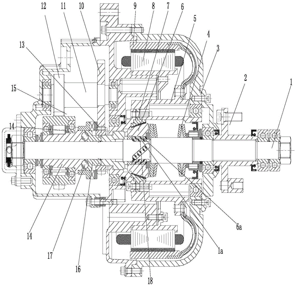
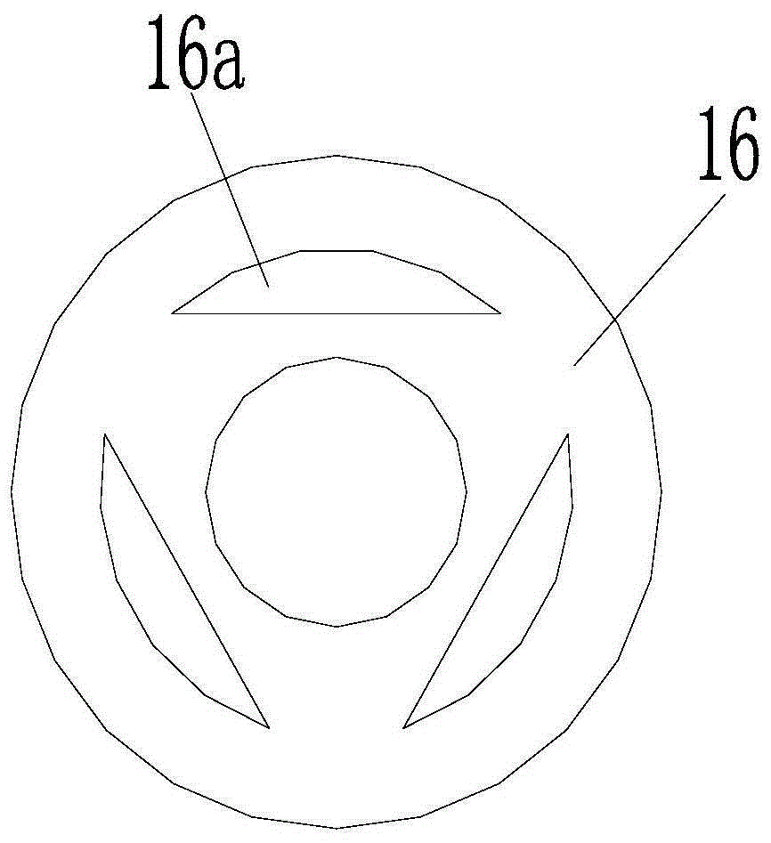
[0026] figure 1 It is a schematic diagram of the axial section structure of the present invention, figure 2 It is a schematic diagram of the structure of the two-way end face cam, as shown in the figure: the electric motorcycle outer rotor motor pendulum type self-adaptive automatic variable speed drive assembly of the present invention includes a drive motor 8, a casing 3, and a casing 3 that rotates and cooperates with the casing 3 and outputs the power The transmission shaft also includes the slow gear transmission mechanism and the mechanical intelligent adaptive transmission assembly arranged on the transmission shaft;

[0027] The mechanical intelligent self-adaptive speed change assembly includes the axial outer tapered sleeve 6 of the annular body, the axial inner tapered sleeve 7 of the annular body and the variable speed elastic element;

[0028] The inner circle of the axial inner tapered sleeve 7 of the ring body is an axial cone surface, the outer circle of the ...


PUM


Abstract

The invention discloses an automatic pendulous self-adaptive speed change driving assembly of an external rotor motor of an electric motorcycle. The automatic pendulous self-adaptive speed change driving assembly comprises a driving motor, a box body, a transmission shaft, a slow-gear transmission mechanism and a mechanical intelligent self-adaptive speed changing assembly. The slow-gear transmission mechanism comprises an overrun clutch and a middle speed reducing transmission mechanism. The overrun clutch transfers and outputs slow-gear power through a slow-gear cam engagement pair. The slow-gear cam engagement pair at least comprises one pendulous end face cam engagement pair. The automatic pendulous self-adaptive speed change driving assembly has all the advantages of an existing automatic cam self-adaptive speed changing device, swing buffer is achieved in the gear shifting process, good stability and smoothness are achieved when an elastic speed reducing piece is released, the abruption feeling and noise are eliminated, and the working efficiency is further improved; the transmission energy consumption in the gear shifting process is reduced, a better energy conservation and consumption reduction effect is achieved, the service life is prolonged, and the automatic pendulous self-adaptive speed change driving assembly is more applicable to light vehicles such as the electric motorcycle.

Description

technical field [0001] The invention relates to a motor vehicle transmission, in particular to a pendulum-type self-adaptive automatic variable speed drive assembly of an outer rotor motor of an electric motorcycle. Background technique [0002] In the prior art, automobiles, motorcycles, and electric bicycles basically directly control the throttle or current control speed through a speed control handle or an accelerator pedal, or use a manual mechanical automatic transmission mechanism to realize speed change. The operation of the handle or the accelerator pedal depends entirely on the operation of the driver, which often results in a mismatch between the operation and the driving conditions, resulting in unstable operation of the motor and stalling. [0003] In motor vehicles, when the rider does not know the driving resistance, the speed change device is only operated and controlled based on experience, which inevitably has the following problems: 1. When starting, going...

Claims


Application Information

Patent Timeline
Patent Type & Authority Applications(China)
IPC IPC(8): F16H61/04F16H61/02
CPCF16H61/0204F16H61/04F16H2306/00
Inventor 梁稚子
Owner SOUTHWEST UNIVERSITY
Why Eureka
Try Eureka