Cooling box

A technology for cooling boxes and boxes, which can be applied to coolers, refrigerated rooms, household refrigeration devices, etc., can solve the problems of high labor intensity for workers, and achieve the effect of reducing labor intensity and ensuring reliability

Inactive Publication Date: 2016-01-06
CHONGQING KANGLE PHARMA
View PDF0 Cites 1 Cited by
  • Summary
  • Abstract
  • Description
  • Claims
  • Application Information

AI Technical Summary

Problems solved by technology

[0003] The purpose of the present invention is to provide a cooling box to solve the problem in the prior art that the material box needs to be pushed or pulled by workers when entering and leaving the box, and the labor intensity of the workers is high

Method used


Image

  • Cooling box

Examples


Embodiment Construction

[0014] Below in conjunction with accompanying drawing and embodiment the technical solution of the present invention is further described:

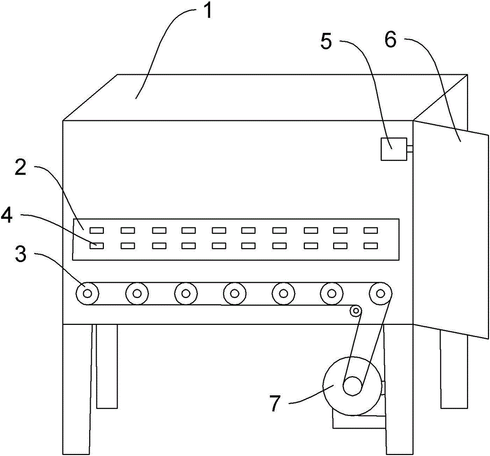
[0015] In the figure: box body 1, limit plate 2, supporting roller 3, roller 4, limit switch 5, discharge door 6, motor 7.

[0016] like figure 1 The cooling box shown includes a bracket, on which a motor 7 is arranged, and a box body 1 is arranged above the motor 7, and the box body 1 is welded to the upper end of the bracket. The left side of the box body 1 is provided with a material inlet and a material inlet door, and the right side is provided with a material outlet and a material outlet door 6 . Both the feed door and the discharge door 6 are provided with a limit switch 5, and the limit switch 5 is electrically connected with the motor 7. When the feed door or the discharge door 6 is opened to 90 o , the limit switch 5 will be triggered, thereby starting the motor 7 to rotate. The bottom of the box body 1 is provided with some ...


PUM


Abstract

The invention relates to production equipment of medicine, in particular to a cooling box. The cooling box comprises a box body. A feeding port and a discharging port are formed in the box body. A feeding door is arranged at the feeding port. A discharging door is arranged at the discharging port. A plurality of parallel carrier rollers are arranged at the bottom of the box body. Chain wheels are arranged on the carrier rollers. A chain is arranged on the chain wheels. A motor is further arranged outside the box body. The chain is connected with the motor. The cooling box has the beneficial effects that the labor intensity of workers is relieved, and the production efficiency is improved.

Description

technical field [0001] The invention relates to production equipment for medicines, in particular to a cooling box. Background technique [0002] In the process of pharmaceutical production, some raw materials need to be sterilized by high temperature before they can be used. Generally, the materials are placed in the material box first, then the material box is put into the high-temperature disinfection room for sterilization, and finally the material box is taken out after being cooled by the cooling box. The bottom of the existing cooling box is a flat plate. The material box needs to be pushed by the worker to enter the cooling box, and the worker needs to pull it out after cooling. Because the material box is relatively heavy after containing the material, it is laborious for the worker to push and pull. Strong. Contents of the invention [0003] The purpose of the present invention is to provide a cooling box to solve the problem in the prior art that the material ...

Claims


Application Information

Patent Timeline
Patent Type & Authority Applications(China)
IPC IPC(8): F25D13/06
Inventor 杨继斌
Owner CHONGQING KANGLE PHARMA
Why Eureka
Try Eureka