

Flange structure applicable to infrared thermal imaging module
An infrared thermal imaging, flange technology, applied in installation, optics, instruments, etc., can solve the problems of waste of resources, high cost, no versatility, etc., and achieve the effect of avoiding excessive rotation, long service life, and wide application range
- Summary
- Abstract
- Description
- Claims
- Application Information
AI Technical Summary
Problems solved by technology
Method used
Image

Examples
Embodiment Construction
[0026] The principles and features of the present invention are described below in conjunction with the accompanying drawings, and the examples given are only used to explain the present invention, and are not intended to limit the scope of the present invention.
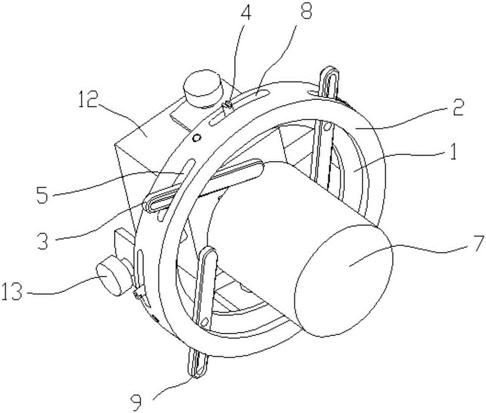
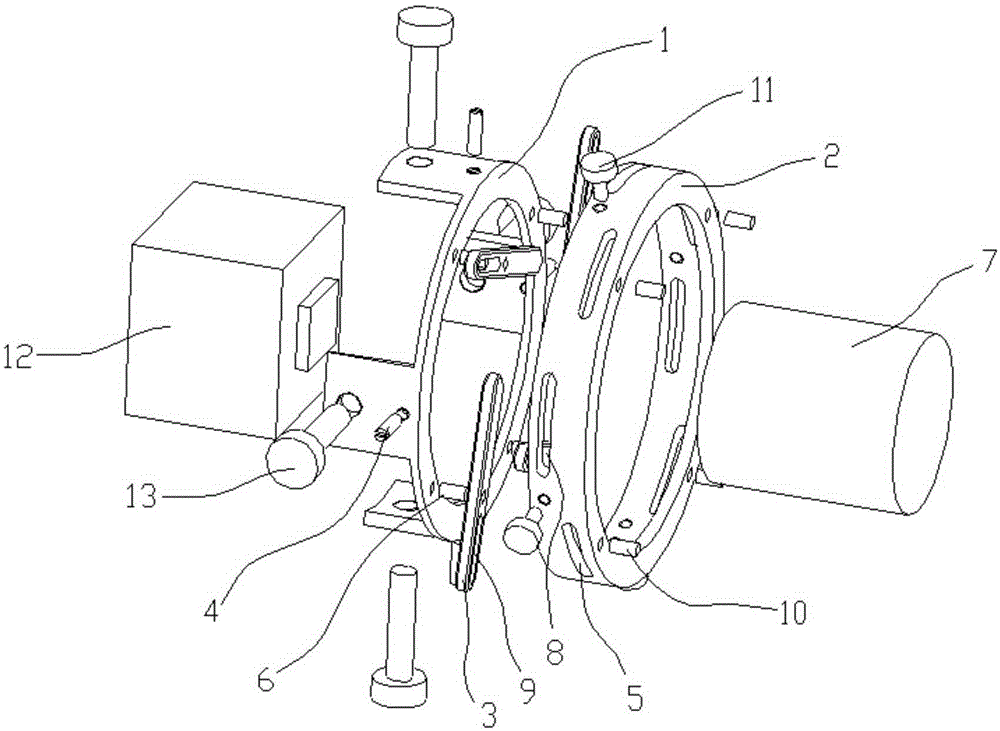
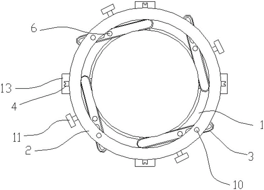
[0027] Such as Figure 1 to Figure 4 As shown, a flange structure suitable for infrared thermal imaging modules includes a core frame 1, a flange ring 2 and claws 3, and the core frame 1 is placed on one side of the flange ring 2, so The core frame 1 is connected with the flange ring 2 through a limit guide nail 4, and the limit guide pin 4 can limit the rotation angle of the flange ring 2 relative to the core frame 1; the flange The ring 2 is provided with a strip-shaped hollow first groove body 5, the claw 3 is placed in the first groove body 5, and the middle part of the claw 3 is rotatably connected with the machine through the rotating shaft 6. The core frame 1 is connected, one end of the claw 3 can touch the...
PUM
 Abstract
Description
Claims
Application Information